
10 U.S. Code § 12733 - Computation of retired pay - 12733
By default, there is no set hole tolerance value. However, you can adjust hole tolerance attributes in the pad and via property dialogs respectively. Hole tolerances and defaults can also be set in the Pad Via Library panel and in the Footprint Library.
You can also choose to group objects by their hole tolerance. From the Drill Symbols dialog (click Configure Drill Symbols in the Drill Table dialog), click Grouping and select Hole Tolerance.
After adding columns to drill table, you must click Okay to exit the Drill Table dialog, or your changes won't be saved.
Hole Tolerance can be accessed and edited in a few different places. Minimum (-) and maximum (+) hole tolerance attributes can be set.
When adding hole tolerance information to pads and vias, unless all pads or vias grouped under the Count column have the same hole tolerance attributes, hole tolerance values will be displayed as an * (asterisk).
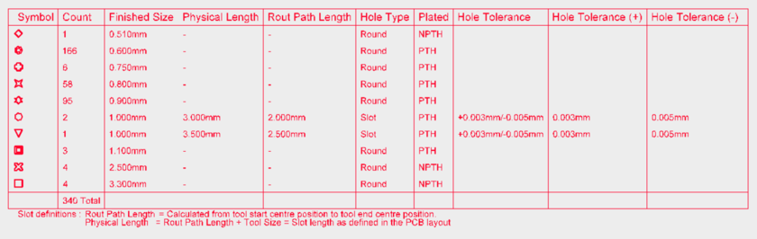
The drill table offers a couple options for viewing hole tolerance options. You can choose whether the drill table uses one or two columns to display tolerance attributes. From the Drill Table Properties dialog, click Add Column. To view all tolerances attributes in one column, select Hole Tolerance. This column will display the minimum and maximum set attributes together. Alternatively, you can choose to display the minimum and maximum set hole tolerance attributes in separate columns. For the latter option, select Hole Tolerance (+) and Hole Tolerance (-). You can of course also choose to display only the minimum or maximum set hole tolerance independently.
Setting hole tolerance attributes can help determine the fits and limits of your board. To make board manufacturing more seamless, Altium Designer 16 now includes the option to add hole tolerance attributes to pads and vias. Hole tolerance columns can be added to, and viewed in, your Drill Table.


 8613869596835