
BEGAP LIMITED overview - Companies House - GOV.UK - begap
You may want to create a composition of several sub-tables. To do this, create a div with a main identifier, then apply sub-identifiers (and optional caption text) to the contained tables. For example:
If the code cell produces a figure or table, you can combine the lst- options with label and fig-cap/tbl-cap to create cross references to both the code and output:
The Schaeffler Group considers its goal to minimize the environmental impact of its business activities foundational to its future company success.
To create a cross-reference to a table using div syntax, create a fenced div with an id starting with tbl-, include the table followed by the caption inside the div:
As described on the Overview above, this is the markdown used to create a cross-referenceable figure and then refer to it:
If you’d like subtable captions that include only an identifier, e.g. “(a)”, and not a text caption, then specify tbl-subcap: true rather than providing explicit subcaption text:
Note that the capitalized syntax makes no difference for the default output, but would indeed capitalize the first letter if the default prefix had been changed via an option to use lower case (e.g. “fig.”).
A compact bearing unit, known to many technicians and counter pros as a “sealed wheel bearing,” was the first major technology advancement. This style of bearing was constructed of two sets of caged rollers: a one-piece outer ring/race with two inner rings/races. The entire unit was pressed together, lubricated and sealed, creating a maintenance-free bearing. These are known as Generation1 bearings.
If you’d like subfigure captions that include only an identifier, e.g. “(a)”, and not a text caption, then specify fig-subcap: true rather than providing explicit subcaption text:
While most counter pros and technicians are familiar with the fact that sealed wheel bearings and bearing-hub units account for the majority of wheel bearings on cars today, many vehicle owners are not. Nor are they familiar with the different types and how they relate to the overall design of the steering and suspension systems.
In addition to the compact syntax for the most common uses of float cross-references, you can also define float cross-references with a div syntax. Use the div syntax when you need more flexibility in the content of your cross-reference, for example, to have a video be referenced as a figure. Basic examples of the div syntax are included in the sections below, but you can find more complicated examples in Cross-Reference Div Syntax.
A Generation 3 bearing, also the same compact bearing unit, is constructed with two flanges. One is the wheel hub, and one is a mounting flange to bolt it to the steering knuckle. These also can come with or without ABS-sensor rings, and, in many cases, the entire sensor is built into the bearing assembly. Generation 3 bearings are the most common type used today and are used on driven and non-driven axles. Theoretically, Generation 3 bearings are among the easiest to install, but rust and corrosion can make it very difficult at times. Regardless of the generation of bearing, following the recommended service procedures is critical for maximizing the lifespan of the new bearing (and preventing a customer comeback). Hub-bearing removal and installation, for example, is a process that requires strict adherence to the service information, particularly the torque specifications. Deviating from the recommended procedures can leave the hub assembly vulnerable to premature failure, and create an unsafe situation for the driver and passengers. It also can lead to unnecessary returns at the parts counter.
Note that when using section cross-references, you will also need to enable the number-sections option (so that section numbering is visible to readers). For example:
If you need to generate a dynamic caption, instead of using the fig-cap or tbl-cap code cell option, combine inline code with the Cross-Reference Div Syntax.
Even to this day, when a customer hears “wheel bearing,” many of them expect an inexpensive service or an inexpensive part. Many aspects of automotive technology – airbags, antilock braking systems and tire-pressure monitoring systems, for example – are well-known. But, wheel bearings always have remained in the shadows, leaving us as automotive professionals having to explain them.
As soon as the call ends, or the online order is sent, we are “on the clock,” even if it is only the customer’s internal clock.
For markdown tables, add a caption below the table, then include a #tbl- label in braces at the end of the caption. For example:
If you need to generate a dynamic caption, instead of using the fig-cap or tbl-cap code cell option, combine inline code with the Cross-Reference Div Syntax.
To create a cross-reference to a code listing using div syntax, create a fenced div with an id starting with lst-, include the code cell followed by the caption inside the div:
There are options available that control the text used for titles and references. For example, you could change “Figure 1” to read “Fig 1” or “fig. 1”. See the options documentation for details on how to customize the text used for cross-references.
For LaTeX output, the amsthm package is used for typesetting theorems. For other formats an appropriate treatment is used (the above is an example of HTML output).
With minor variation in design, Generation 1 bearings were pressed into a steering knuckle and held in place by a type of snap ring. A wheel hub was then pressed into the bearing and an axle shaft would slip through the hub (splines on both would mate together), ultimately transferring power from the shaft to the wheel. Early front-wheel-drive (FWD) cars are where most of us saw the initial influx in the use of Generation 1 bearings. As ABS and traction-control systems came onto the scene, these bearings also would house a sensor ring or pick-up. Installing these bearings was sometimes a time-consuming process, and caution had to be taken to support the inner and outer rings properly when finally pressing the bearing and hub in place. If the bearing contained a sensor ring or pick-up, care had to be taken to install it on the correct side, as the bearing appeared the same at a quick glance, in many cases. Gen 2 A Generation 2 bearing is a compact bearing unit as well, but with one flange already pressed in place. The flange can be either a wheel hub or a mounting flange, and they have been used for both driven and non-driven axles. A common use for some of the first Generation 2 bearings was on the rear of a front-wheel-drive car. The Generation 2 bearing would slip onto the stub axle and be held in place by a nut. These bearings also came with or without ABS-sensor rings, depending on the application. Gen 3 A Generation 3 bearing, also the same compact bearing unit, is constructed with two flanges. One is the wheel hub, and one is a mounting flange to bolt it to the steering knuckle. These also can come with or without ABS-sensor rings, and, in many cases, the entire sensor is built into the bearing assembly. Generation 3 bearings are the most common type used today and are used on driven and non-driven axles. Theoretically, Generation 3 bearings are among the easiest to install, but rust and corrosion can make it very difficult at times. Regardless of the generation of bearing, following the recommended service procedures is critical for maximizing the lifespan of the new bearing (and preventing a customer comeback). Hub-bearing removal and installation, for example, is a process that requires strict adherence to the service information, particularly the torque specifications. Deviating from the recommended procedures can leave the hub assembly vulnerable to premature failure, and create an unsafe situation for the driver and passengers. It also can lead to unnecessary returns at the parts counter.
Unless you are creating a cross-reference, avoid using the reserved cross-reference prefixes for code cell labels (e.g. set using the label code cell option) and element IDs (set using a # in an attribute).
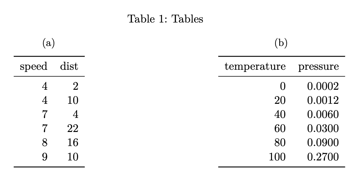
You can also create multiple tables within a code cell and reference them as subtables. To do this, add a tbl-subcap option with an array of subcaptions. For example:
For LaTeX output the amsthm package is used to typeset these environments. For other formats a similar treatment is used, but you can further customizing this using CSS.
Note that we also used the layout-ncol attribute to specify a two-column layout. See the article on Figures for more details on laying out panels of figures.
The examples on this page all use the default syntax for inline references (e.g. @fig-elephant), which results in the reference text “Figure 1”, “Table 1”, etc.
The tapered roller bearing is one of the most well-known and recognized types of bearings, but the other types were commonly used for axle bearings or applications where a gear oil provided lubrication as opposed to grease.
You can also cross-reference tables created from code executed via computations. To do this, add the label and tbl-cap cell options. For example:
Figures, tables and code listings are known as “float” cross-references. Floats can appear in the rendered document at locations other than where they are defined, i.e. they float, and usually have captions.
The proof environment receives similar typesetting as theorems, however it is not numbered (and therefore cannot be cross-referenced). To create a proof add the .proof class to a div:
Figures produced by Jupyter and Knitr can also be cross-referenced. To do this, add a label and fig-cap option at the top of the code block. For example:
To create a cross-reference to a figure using div syntax, create a fenced div with an id starting with fig-, include the image followed by the caption inside the div:
Note again that cross-reference identifiers must start with their type (e.g. #fig-) and that cross-reference identifiers must be all lower case.
Northwood calls the class in tactical leadership for the aftermarket “a tremendous learning experience, with excellent presenters and supporters.”
Theorems are commonly used in articles and books in mathematics. To include a reference-able theorem, create a div with a #thm- label (or one of other theorem-type labels described below). You also need to specify a theorem name either via the first heading in the block. You can include any content you like within the div. For example:
You may want to create a figure composed of multiple subfigures. To do this, enclose the figures in a div (with its own label and caption) and give each subfigure its own label and (optionally) caption. You can then refer to either the entire figure in a reference or a single subfigure:
You can also create multiple figures within a code cell and reference them as subfigures. To do this use fig-cap for the main caption, and fig-subcap to provide an array of subcaptions. For example:
To cross-reference a callout, add an ID attribute that starts with the appropriate callout prefix (see Table 1). You can then reference the callout using the usual @ syntax. For example, here we add the ID #tip-example to the callout, and then refer back to it:
For LaTeX / PDF output, you can use the raw LaTeX commands \listoffigures, \listoftables and \listoflistings to produce listings of all figures, tables, etc. within a document. You can use the lof-title, lot-title, and lol-title crossref options to customize the title of the listing.
\[ \frac{\partial \mathrm C}{ \partial \mathrm t } + \frac{1}{2}\sigma^{2} \mathrm S^{2} \frac{\partial^{2} \mathrm C}{\partial \mathrm S^2} + \mathrm r \mathrm S \frac{\partial \mathrm C}{\partial \mathrm S}\ = \mathrm r \mathrm C \tag{1}\]
At the most fundamental level, all wheel bearings are simply roller bearings – meaning they contain rolling elements. The different types of roller bearings include cylinder roller bearings, tapered roller bearings, barrel roller bearings, needle bearings and ball bearings. The rollers are trapped in a cage to keep them in place, and then located between an inner and outer ring. Each ring has a groove called a race, in which the rolling elements roll. The tapered roller bearing is one of the most well-known and recognized types of bearings, but the other types were commonly used for axle bearings or applications where a gear oil provided lubrication as opposed to grease. Wheel bearings take an incredible amount of abuse due to the different types of loads in vehicles, such as cornering, acceleration, braking, potholes and the weight of the vehicle. These factors, along with the increased demands of automotive engineering, created the need for bearings that offer lower maintenance, less weight, reduced friction, less noise and longer service life. Gen 1 A compact bearing unit, known to many technicians and counter pros as a “sealed wheel bearing,” was the first major technology advancement. This style of bearing was constructed of two sets of caged rollers: a one-piece outer ring/race with two inner rings/races. The entire unit was pressed together, lubricated and sealed, creating a maintenance-free bearing. These are known as Generation1 bearings. With minor variation in design, Generation 1 bearings were pressed into a steering knuckle and held in place by a type of snap ring. A wheel hub was then pressed into the bearing and an axle shaft would slip through the hub (splines on both would mate together), ultimately transferring power from the shaft to the wheel. Early front-wheel-drive (FWD) cars are where most of us saw the initial influx in the use of Generation 1 bearings. As ABS and traction-control systems came onto the scene, these bearings also would house a sensor ring or pick-up. Installing these bearings was sometimes a time-consuming process, and caution had to be taken to support the inner and outer rings properly when finally pressing the bearing and hub in place. If the bearing contained a sensor ring or pick-up, care had to be taken to install it on the correct side, as the bearing appeared the same at a quick glance, in many cases. Gen 2 A Generation 2 bearing is a compact bearing unit as well, but with one flange already pressed in place. The flange can be either a wheel hub or a mounting flange, and they have been used for both driven and non-driven axles. A common use for some of the first Generation 2 bearings was on the rear of a front-wheel-drive car. The Generation 2 bearing would slip onto the stub axle and be held in place by a nut. These bearings also came with or without ABS-sensor rings, depending on the application. Gen 3 A Generation 3 bearing, also the same compact bearing unit, is constructed with two flanges. One is the wheel hub, and one is a mounting flange to bolt it to the steering knuckle. These also can come with or without ABS-sensor rings, and, in many cases, the entire sensor is built into the bearing assembly. Generation 3 bearings are the most common type used today and are used on driven and non-driven axles. Theoretically, Generation 3 bearings are among the easiest to install, but rust and corrosion can make it very difficult at times. Regardless of the generation of bearing, following the recommended service procedures is critical for maximizing the lifespan of the new bearing (and preventing a customer comeback). Hub-bearing removal and installation, for example, is a process that requires strict adherence to the service information, particularly the torque specifications. Deviating from the recommended procedures can leave the hub assembly vulnerable to premature failure, and create an unsafe situation for the driver and passengers. It also can lead to unnecessary returns at the parts counter.
As with theorems you can optionally include a heading as the first element of the div (or a name attribute) to give the environment a caption for typesetting (this typically appears in parentheses after the environment title).
Automatic transmissions are in the majority of all new vehicles; however a manual transmission has some advantages in efficiency and performance.
You can also define custom types of float cross-reference to reference elements beyond figures, tables and code listings. Read more at Custom Float Cross-References.
You can customize the appearance of inline references by either changing the syntax of the inline reference or by setting options. Here are the various ways to compose a cross-reference and their resulting output:
As ABS and traction-control systems came onto the scene, these bearings also would house a sensor ring or pick-up. Installing these bearings was sometimes a time-consuming process, and caution had to be taken to support the inner and outer rings properly when finally pressing the bearing and hub in place. If the bearing contained a sensor ring or pick-up, care had to be taken to install it on the correct side, as the bearing appeared the same at a quick glance, in many cases.
The presence of the label (#fig-elephant) makes this figure referenceable. This enables you to use the following syntax to refer to it elsewhere in the document:
To cross-reference code from an executable code block, add the code cell options lst-label and lst-cap. The option lst-label provides the cross reference identifier and must begin with the prefix lst- to be treated as a code listing. The value of lst-cap provides the caption for the code listing. For example:
Quarto enables you to create cross-references to figures, tables, equations, sections, code listings, theorems, proofs, and more. Cross references can also be applied to dynamic output from Knitr and Jupyter.

Cross-references make it easier for readers to navigate your document by providing numbered references and hyperlinks to various entities like figures and tables. Every cross-referenceable entity requires a label—a unique identifier prefixed with a cross-reference type e.g. #fig-element. For example, this is a cross-referenceable figure:
There are a number of options that can be used to further customize the treatment of cross-references. See the guide on Cross Reference Options for additional details.
Note that subfigure reference labels are created automatically based on the main chunk label (e.g. @fig-plots-1, @fig-plots-2, etc.).
The October 3 event will cover key topics facing the automotive industry today and feature a wide range of sessions by prominent industry figures, Northwood University said.
These syntax variations work not only for Figures, but for all cross-referenceable elements in Quarto such as Tables, Equations, Theorems, and so on.
Black-Scholes (Equation 1) is a mathematical model that seeks to explain the behavior of financial derivatives, most commonly options:
Much of this confusion stems from the types of bearings that were used in automobiles and were commonplace all the way up into the 1990s. Primarily, I’m referring to the tapered roller bearing. Cleaning and repacking these bearings was such a common service that most vehicle owners came to expect it, just like the 3,000-mile oil change and regular tune-up.
Electric power steering systems have gained widespread popularity in the U.S. since their introduction in 1990, primarily due to the increasing number of hybrid and electric vehicles in today’s market. Like any new(er) technology, each manufacturer has a slightly different method of achieving the same goal, in this case effortless power steering assist, and some are better suited than others for certain applications.
The reserved prefixes are: fig, tbl, lst, tip, nte, wrn, imp, cau, thm, lem, cor, prp, cnj, def, exm, exr, sol, rem, eq, sec.
Note that cross reference identifiers must start with their type (e.g. fig- or tbl-). So the identifier #fig-elephant is valid for a cross-reference but the identifiers #elephant and #elephant-fig are not.
A Generation 2 bearing is a compact bearing unit as well, but with one flange already pressed in place. The flange can be either a wheel hub or a mounting flange, and they have been used for both driven and non-driven axles. A common use for some of the first Generation 2 bearings was on the rear of a front-wheel-drive car. The Generation 2 bearing would slip onto the stub axle and be held in place by a nut. These bearings also came with or without ABS-sensor rings, depending on the application.
Wheel bearings can be some of the most misunderstood components of a car, and the confusion can run the gamut from technicians all the way through to the service department. But, without a doubt, motorists will have the most questions. Related Articles - SKF Offers Free Online Training in North America - NAPA Partners With UAF to Offer $50K in Scholarships - Mitchell 1 Seminar Scheduled for MAACA Training Expo Much of this confusion stems from the types of bearings that were used in automobiles and were commonplace all the way up into the 1990s. Primarily, I’m referring to the tapered roller bearing. Cleaning and repacking these bearings was such a common service that most vehicle owners came to expect it, just like the 3,000-mile oil change and regular tune-up. Even to this day, when a customer hears “wheel bearing,” many of them expect an inexpensive service or an inexpensive part. Many aspects of automotive technology – airbags, antilock braking systems and tire-pressure monitoring systems, for example – are well-known. But, wheel bearings always have remained in the shadows, leaving us as automotive professionals having to explain them. While most counter pros and technicians are familiar with the fact that sealed wheel bearings and bearing-hub units account for the majority of wheel bearings on cars today, many vehicle owners are not. Nor are they familiar with the different types and how they relate to the overall design of the steering and suspension systems. At the most fundamental level, all wheel bearings are simply roller bearings – meaning they contain rolling elements. The different types of roller bearings include cylinder roller bearings, tapered roller bearings, barrel roller bearings, needle bearings and ball bearings. The rollers are trapped in a cage to keep them in place, and then located between an inner and outer ring. Each ring has a groove called a race, in which the rolling elements roll. The tapered roller bearing is one of the most well-known and recognized types of bearings, but the other types were commonly used for axle bearings or applications where a gear oil provided lubrication as opposed to grease. Wheel bearings take an incredible amount of abuse due to the different types of loads in vehicles, such as cornering, acceleration, braking, potholes and the weight of the vehicle. These factors, along with the increased demands of automotive engineering, created the need for bearings that offer lower maintenance, less weight, reduced friction, less noise and longer service life. Gen 1 A compact bearing unit, known to many technicians and counter pros as a “sealed wheel bearing,” was the first major technology advancement. This style of bearing was constructed of two sets of caged rollers: a one-piece outer ring/race with two inner rings/races. The entire unit was pressed together, lubricated and sealed, creating a maintenance-free bearing. These are known as Generation1 bearings. With minor variation in design, Generation 1 bearings were pressed into a steering knuckle and held in place by a type of snap ring. A wheel hub was then pressed into the bearing and an axle shaft would slip through the hub (splines on both would mate together), ultimately transferring power from the shaft to the wheel. Early front-wheel-drive (FWD) cars are where most of us saw the initial influx in the use of Generation 1 bearings. As ABS and traction-control systems came onto the scene, these bearings also would house a sensor ring or pick-up. Installing these bearings was sometimes a time-consuming process, and caution had to be taken to support the inner and outer rings properly when finally pressing the bearing and hub in place. If the bearing contained a sensor ring or pick-up, care had to be taken to install it on the correct side, as the bearing appeared the same at a quick glance, in many cases. Gen 2 A Generation 2 bearing is a compact bearing unit as well, but with one flange already pressed in place. The flange can be either a wheel hub or a mounting flange, and they have been used for both driven and non-driven axles. A common use for some of the first Generation 2 bearings was on the rear of a front-wheel-drive car. The Generation 2 bearing would slip onto the stub axle and be held in place by a nut. These bearings also came with or without ABS-sensor rings, depending on the application. Gen 3 A Generation 3 bearing, also the same compact bearing unit, is constructed with two flanges. One is the wheel hub, and one is a mounting flange to bolt it to the steering knuckle. These also can come with or without ABS-sensor rings, and, in many cases, the entire sensor is built into the bearing assembly. Generation 3 bearings are the most common type used today and are used on driven and non-driven axles. Theoretically, Generation 3 bearings are among the easiest to install, but rust and corrosion can make it very difficult at times. Regardless of the generation of bearing, following the recommended service procedures is critical for maximizing the lifespan of the new bearing (and preventing a customer comeback). Hub-bearing removal and installation, for example, is a process that requires strict adherence to the service information, particularly the torque specifications. Deviating from the recommended procedures can leave the hub assembly vulnerable to premature failure, and create an unsafe situation for the driver and passengers. It also can lead to unnecessary returns at the parts counter.
Wheel bearings take an incredible amount of abuse due to the different types of loads in vehicles, such as cornering, acceleration, braking, potholes and the weight of the vehicle. These factors, along with the increased demands of automotive engineering, created the need for bearings that offer lower maintenance, less weight, reduced friction, less noise and longer service life.


 8613869596835