
How Much Does It Cost to Fix a Wheel Bearing? - bearing cost car
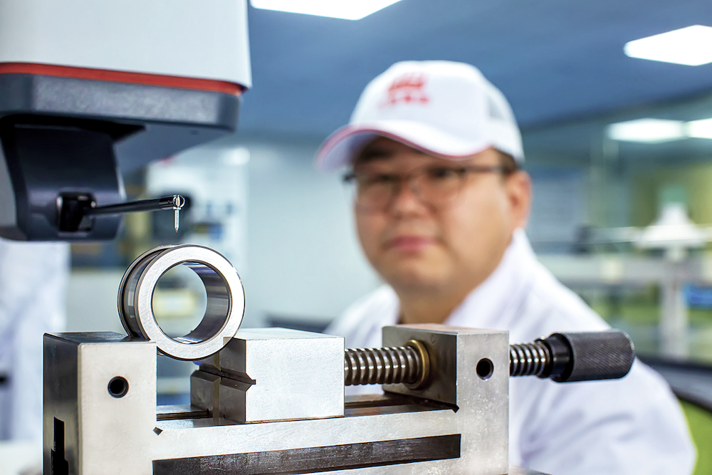
We source our high-quality 99.98% VIM steel and move it directly into our production facility where grinding, turning, heat-treating, assembly, and washing occurs. Our quality assurance and control teams constantly evaluate our product until they ship to the customer.
WD Bearing manufacturing headquarters is a 20,000 m² facility with a dedicated 140 m² quality and inspection room. Our engineering labs in Europe and North America extend our quality control, service, and sales to the entire world. Our global presence ensures that our customers receive local support from our dedicated sales and service teams, regardless of their location worldwide.
American rollerbearing
BearingFactory
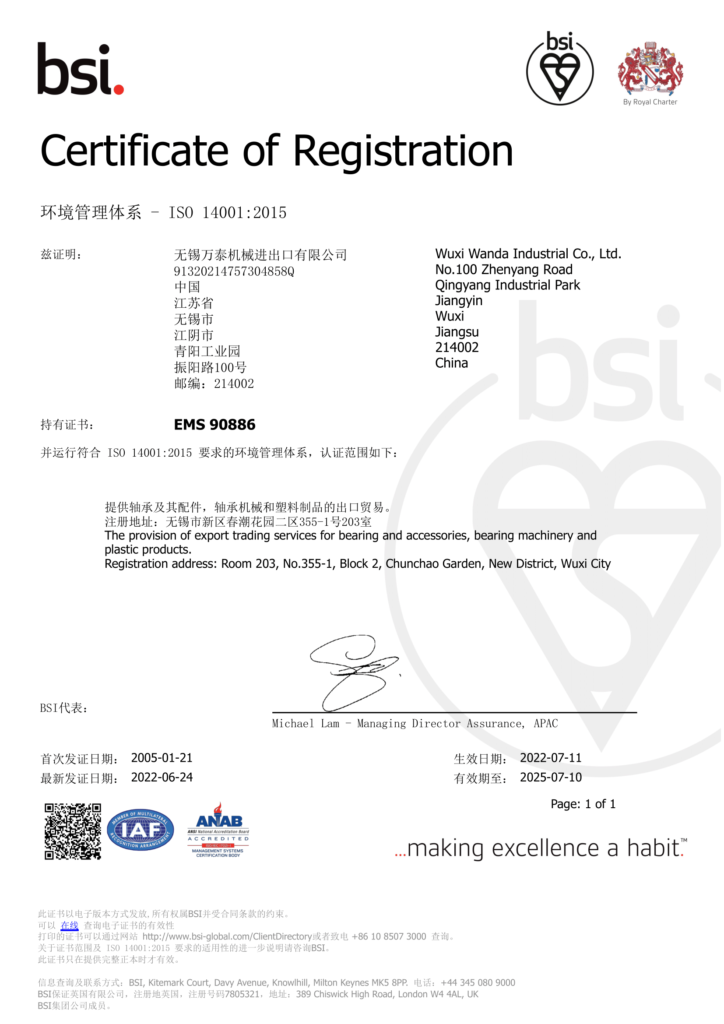
WD Bearing Group is proud to manufacture products in accordance with Six Sigma principles and quality management systems including ISO 9001, ISO 14001, and IATF 16949. We continuously invest in advanced machining equipment, professional bearing software, and highly skilled employees. This focus makes WD Bearing Group the customer’s preferred partner for bearing technology, and bearing manufacturing services.
StrongWind, a Canadian based company produces a patented urban VAWT which has been installed in several Canadian and international locations as of 2023.[31]
Where C p {\displaystyle C_{p}} is the power coefficient, ρ {\displaystyle \rho } is air density, A {\displaystyle A} is the swept area of the turbine, and ν {\displaystyle \nu } is the wind speed.[10]
WD Bearing Group is a technology-oriented bearing company specializing in research & development, manufacturing, sales, and service of high-quality bearings.
Bearingmanufacturer
A 2021 study simulated a VAWT configuration that allowed VAWTs to beat a comparable HAWT installation by 15%. An 11,500-hour simulation demonstrated the increased efficiency, in part by using a grid formation. One effect is to avoid downstream turbulence stemming from grid-arranged HAWTs that lowers efficiency. Other optimizations included array angle, rotation direction, turbine spacing, and number of rotors.[23]
At WD, our advanced bearing manufacturing process is engineered to empower your success across diverse applications, ensuring you have the robust capabilities necessary to excel in your industry.
Drag-type VAWTs such as the Savonius rotor typically operate at lower tip speed ratios than lift-based VAWTs such as Darrieus rotors and cycloturbines.
Other than the drag-types, VAWTs have proven less reliable than HAWTs,[20] although modern designs have overcome many early issues.[21][22]
The Darrieus wind turbine is a lift-type VAWT. The original design included a number of curved aerofoil blades with the tips attached on a rotating shaft. However, there are also designs that use straight vertical airfoils, referred to as H-rotor or Giromill Darrieus wind turbines. Furthermore, the blades of the Darrieus wind turbine can be shaped into a helix to reduce the torque ripple effect on the turbine by spreading the torque evenly over the revolution.
RBCbearing
A vertical-axis wind turbine (VAWT) is a type of wind turbine where the main rotor shaft is set transverse to the wind while the main components are located at the base of the turbine. This arrangement allows the generator and gearbox to be located close to the ground, facilitating service and repair. VAWTs do not need to be pointed into the wind,[1][2] which removes the need for wind-sensing and orientation mechanisms. Major drawbacks for the early designs (Savonius, Darrieus and giromill) included the significant torque ripple during each revolution and the large bending moments on the blades. Later designs addressed the torque ripple by sweeping the blades helically (Gorlov type).[3] Savonius vertical-axis wind turbines (VAWT) are not widespread, but their simplicity and better performance in disturbed flow-fields, compared to small horizontal-axis wind turbines (HAWT) make them a good alternative for distributed generation devices in an urban environment.[4]
The forces and the velocities acting in a Darrieus turbine are depicted in Figure 1. The resultant velocity vector, W → {\displaystyle {\vec {W}}} , is the vectorial sum of the undisturbed upstream air velocity, U → {\displaystyle {\vec {U}}} , and the velocity vector of the advancing blade, − ω → × R → {\displaystyle -{\vec {\omega }}\times {\vec {R}}} .
The resultant aerodynamic force is resolved either into lift (L) - drag (D) components or normal (N) - tangential (T) components. The forces are considered to be acting at the quarter-chord point, and the pitching moment is determined to resolve the aerodynamic forces. The aeronautical terms lift and drag refer to the forces across (lift) and along (drag) the approaching net relative airflow. The tangential force acts along the blade's velocity, pulling the blade around, and the normal force acts radially, pushing against the shaft bearings. The lift and the drag force are useful when dealing with the aerodynamic forces around the blade such as dynamic stall, boundary layer etc.; while when dealing with global performance, fatigue loads, etc., it is more convenient to have a normal-tangential frame. The lift and the drag coefficients are usually normalised by the dynamic pressure of the relative airflow, while the dynamic pressure of undisturbed upstream fluid velocity usually normalises the normal and tangential coefficients.
Timken
Our vision for you is one that blends simplicity with expertise. Experience our seamless approach where your needs are met without complexities.
Take advantage of our award-winning engineering and sales teams to secure the optimal bearing solution for your requirements.
Various simple designs may exist for vertical wind turbines, as detailed below. In practice, you may come across a range of variations and combinations, with developers frequently demonstrating their creativity in crafting diverse forms of vertical wind turbines.
There are two main types of Vertical Axis Wind Turbines. I.e. Savonius Wind turbine and Darrieus wind turbine. The Darrieus rotor comes in various subforms, including helix-shaped, disc-like, and the H-rotor with straight blades. These turbines typically have three slim rotor blades driven by lift forces, allowing them to achieve high speeds.[1]
A vertical axis wind turbine has its axis perpendicular to the wind streamlines and vertical to the ground. A more general term that includes this option is a "transverse axis wind turbine" or "cross-flow wind turbine". For example, the original Darrieus patent, US patent 1835018, includes both options.
Computer modelling suggests that vertical-axis wind turbines arranged in wind farms may generate more than 15% more power per turbine than when acting in isolation.[5][6]
A = Blade Area (not to be confused with the Swept Area, which is equal to the height of the blade/rotor times the rotor diameter), R = Radius of turbine
NTNBearing
Discover your opportunities with our risk-free application review and have recommendations within days, not weeks.
When the velocity of a VAWT wind turbine grows, so does the power, however at a certain peak point, the power progressively decreases to zero even while the wind turbine velocity is at its greatest.[clarification needed] Such that, disc brakes are used to slow the velocity of a wind turbine at high wind conditions. However, sometimes due to disc brake overheating, the turbine can catch fire.[16]
SKFbearing
The Savonius wind turbine (SWT) is a drag-type VAWT. The common design includes a rotating shaft with two or three scoops that catch the incoming wind. Due to its simplistic and robust design and its relatively low efficiency it is used whenever reliability is more important than efficiency. One reason for the low efficiency of a Savonius wind turbine is that roughly only half of the turbine generates positive torque, while the other side moves against the wind and thus produces negative torque. A variant of SWT is the Harmony wind turbine[11] with helix-shaped blades and an automatic furling mechanism during high-speed wind conditions.
In 2011, Sandia National Laboratories wind-energy researchers began a five-year study of applying VAWT design technology to offshore wind farms.[27] The researchers stated: "The economics of offshore windpower are different from land-based turbines, due to installation and operational challenges. VAWTs offer three big advantages that could reduce the cost of wind energy: a lower turbine center of gravity; reduced machine complexity; and better scalability to very large sizes. A lower center of gravity means improved stability afloat and lower gravitational fatigue loads. Additionally, the drivetrain on a VAWT is at or near the surface, potentially making maintenance easier and less time-consuming. Fewer parts, lower fatigue loads and simpler maintenance all lead to reduced maintenance costs."
The Windspire, a small VAWT intended for individual (home or office) use was developed in the early 2000s by US company Mariah Power. The company reported that several units had been installed across the US by June 2008.[25]
WD bearings are frequently supplied to OEMs in several industries including material handling , agriculture , construction , pump and compressor , gearbox , electric motor, and more.
Thus the oncoming fluid velocity varies during each cycle. Maximum velocity is found for θ = 0 ∘ {\displaystyle \theta =0{}^{\circ }} and the minimum is found for θ = 180 ∘ {\displaystyle \theta =180{}^{\circ }} , where θ {\displaystyle \theta } is the azimuthal or orbital blade position. The angle of attack, α {\displaystyle \alpha } , is the angle between the oncoming air speed, W, and the blade's chord. The resultant airflow creates a varying, positive angle of attack to the blade in the upstream zone of the machine, switching sign in the downstream zone of the machine.

Our mission is to stoke the common good between business and mankind by supplying the world with quality bearings and crafting meaningful partnerships.
Dulas, Anglesey, received permission in March 2014 to install a prototype VAWT on the breakwater at Port Talbot waterside. The turbine is a new design, supplied by Wales-based C-FEC (Swansea),[29] and will be operated for a two-year trial.[30] This VAWT incorporates a wind shield which blocks the wind from the advancing blades, and thus requires a wind-direction sensor and a positioning mechanism, as opposed to the "egg-beater" types of VAWTs discussed above.[29]
Architect Michael Reynolds (known for his Earthship house designs) developed a 4th-generation VAWT named Dynasphere. It has two 1.5 kW generators and can produce electricity at very low speeds.[32]
WD Bearing Group has crafted a team with hundreds of years of engineering experience collectively. Our engineers have developed applications used by NASA on the Mars rover, the construction of the World Trade Center, and numerous bearing-specific applications with popular OEMs around the world.
Arborwind, an Ann Arbor, Michigan, based company, produces a patented small VAWT which has been installed at several US locations as of 2013.[26]
In 2022 Norway's World Wide Wind introduced floating VAWTs with two sets of counter-rotating blades. The two sets are fixed to concentric shafts. Each has an attached turbine. One is attached to the rotor, the other to the stator. This has the effect of doubling their speed relative to each other versus a static stator. They claimed to more than double the output compared to the largest HAWTs. HAWTs require heavy drivetrains, gearboxes, generators and blades at the top of the tower, necessitating heavy underwater counterbalances. VAWTs place most of the heavy components at the bottom of the tower, reducing the need for counterbalance. The blades sweep a conical area, which helps reduce the turbulence downwind of each tower, increasing the maximum tower density. The company claims it will build a 400 m (1,300 ft) 40-megawatt unit.[24]
BearingCompany
Being lift-type devices, the Darrieus wind turbines can extract more power from the wind than drag-type wind turbines, such as the Savonius wind turbine.
The blades of a VAWT are fatigue-prone due to the wide variation in applied forces during each rotation. The vertically oriented blades can twist and bend during each turn, shortening their usable lifetimes.
Thus, combining the above with the definitions for the tip speed ratio λ = ( ω R ) / U {\displaystyle \lambda =(\omega R)/U} yields the following expression for the resultant velocity:
Revolving wing wind turbines or rotating wing wind turbines are a new category of lift-type VAWTs which use 1 vertically standing, non-helical airfoil to generate 360-degree rotation around a vertical shaft that runs through the center of the airfoil.
A 24-unit VAWT demonstration plot was installed in southern California in the early 2010s by Caltech aeronautical professor John Dabiri. His design was incorporated in a 10-unit generating farm installed in 2013 in the Alaskan village of Igiugig.[28]


 8613869596835