
Hub Assembly Torque Specs Needed - torque specs wheel hub assembly
How to measurecylinderborewith micrometer
First and foremost, keep your micrometers clean and lightly oiled. Always store your micrometers back in their cases or boxes when not in use. Don’t just toss them on the workbench when you are done. Even when you have the micrometer in use, don’t just lay it down on the workbench. Place a clean cotton towel down first and then place your micrometer on that cloth after you take a reading.
How to measurecylinder size
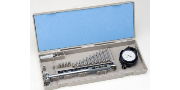
A dial bore gauge setting fixture is way more than a fancy micrometer. It’s easier to use, much more stable, resulting in more accurate readings and the novice can learn faster how to set up dial bore gauges.
Cylinderboresize chart
Using the setting fixture: Locate the correct standard for the bore size you are going to measure. Place the standard into the setting fixture. Zero the spindle on the setting fixture. Remove the standard, and place the dial bore gauge into the setting fixture. Now you can rotate the spindle and adjust the dial indicator for zero on the bore gauge to match zero on the setting fixture.
Never, and I mean never use any type of abrasive or emery to clean your micrometers. Remember, micrometers are not C-clamps. Take time every month and confirm your micrometers are properly calibrated to ensure they read accurately.

LRT61010 | Metric Inner Race | 6X10X10 ... The UK's leading wholesale bearing, belt and power transmission distributor! In partnership with a number of world ...
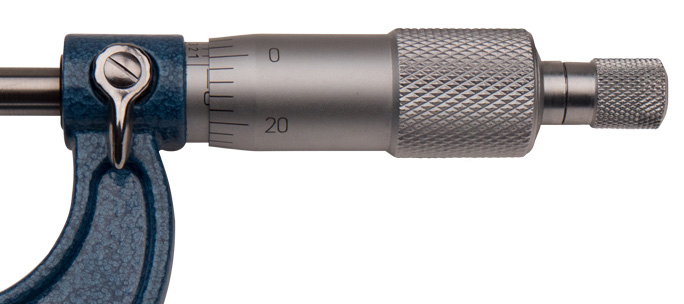
Place the standard between the anvil and the spindle and rotate the spindle until it makes contact with the standard. In this case I am using a 1˝ standard. The reading on the micrometer is supposed to be exactly 1˝. In other words, all the corresponding lines will line up perfectly if the micrometer is in fact calibrated. If they don’t, then take the spanner wrench and move the inner sleeve until it lines up perfectly with the lines 0027, 0028, and 0030.
Find parts that fit. We need more information about your vehicle to confirm fit. Add ...
The amount of contact (all-important feel) is up to you, the machinist. When you are attempting to measure 0.0001˝, ensuring that the micrometer is repeating the same true reading time after time is critical and directly related to how much pressure you use each time. Because human beings’ hand pressure can vary so widely, this can be a source of serious error in measurement.
How to measure engine boreat home
First step: measure something, and note the reading. Measure it again and compare the reading. Do they match? Make a note if they do not match. Next, rotate the thimble all the way down until the spindle makes contact with the anvil. Note the position of spindle. Is it reading zero to zero? If not then it is time to calibrate. A real indication on whether your micrometer is calibrated or not is to simply measure something of a known size and if you constantly get a different reading, then your micrometer is off and needs calibrating.
How to measurecylinder diameter
There’s a lot to talk about, but I am going to focus on the two most popular measuring tools for this article : the micrometer and the dial bore gauge.
When it comes to favorite seasons among our industry, it would be tough to beat the summer months. Sure, it gets hot, but it’s this time of year that our industry is out traveling the country for various shows, events, and of course races – and we’re there for it. June was a very busy
One of the best dial bore setting fixtures is made by Sunnen but other models are available. You can also use what we just talked about – a micrometer. If you are going to use a micrometer, I highly recommend you get yourself the “third” hand. The third hand is a soft vise that holds your micrometer while you set your dial bore gauge.
The live 18108 train running status feature makes your journey between source and destination stations convenient, ensuring you reach your boarding point in ...
A micrometer is an instrument used for measuring extremely small distances. To use one, you start by bringing the micrometer close to the range you are going to measure. Do this by rolling the thimble along your hand or arm – do not ever and I mean never let me see you twirling a micrometer!
Speedi-Sleeve® Replacement Shaft Wear Sleeve ; Vendor: Applied Industrial Technologies ; Vendor SKU: 100915624 ; Manufacturer: Chicago Rawhide ; MPN: 84590 ; Shaft ...
Now you are ready to measure the cylinder bore using your dial bore gauge as a plus/minus measuring tool. Measure the bore in X and then Y direction at the top, middle and bottom of each cylinder bore. Make sure you get as close to the bottom of the bore as possible for the lower measurement. Be sure to write these dimensions down. Remember to hit no less than six to nine positions from top to bottom of the cylinder bore. This will determine the size of the bore as well as show any out-of-roundness or funnel, or hourglass shape of the cylinder.
I’ve got one more thing to say. If you are working on anything metric, measure in metric. You simply cannot use a 5/16 ˝ reamer in an 8mm valve guide or a 1/2˝ socket on 12mm nut, so how do you expect to use a decimal or fractional micrometer to measure metric dimensions? You can’t! Sure you can do the math or reference your decimal equivalent chart (that you got from your favorite shop supply company) but you really need to step up and buy a metric micrometer or dial bore gauge or dial indicator to do it right! Got it? Good! See ya in the shop.
Lock down the adjustment nut securely and repeat rotating the spindle until it makes contact with the anvil. Does it now read zero to zero? If so you have done well. If not, go back through the procedure again until you get it right.
May 29, 2020 — It made a grinding sound. At first i thought it was just while turning it left, but turns out its coming no matter which way i turn the steering.
When placing the micrometer onto the part, hold it firmly in place with one hand. Close the micrometer using the ratchet until the spindle is nearly on the measured part. This usually can be determined visually. If you hit the part before expected, back off slightly and then slowly and gently close the spindle until the ratchet stop disengages one click.
How to measurecylinderborewith caliper
When it comes to favorite seasons among our industry, it would be tough to beat the summer months. Sure, it gets hot, but it’s this time of year that our industry is out traveling the country for various shows, events, and of course races – and we’re there for it.
With all dial bore gauges you change anvils and spacers of certain sizes, according to the bore size you are measuring. There is also a dial bore gauge out there that allows you to measure main or cam bores through the cylinder bore, thereby keeping the dial bore gauge in a vertical versus horizontal position. It’s called the 90-degree dial bore gauge.
Happy New Year everyone! I trust you all enjoyed the holiday season and are hitting the gas full throttle now that we’re in a new year and January is already flying by. Personally, I’m not generally big on making resolutions – at least not ones that require tons of effort or ones I know I
Well, engines have changed significantly due to very lightweight components, different methods for sealing gaskets and in some cases no gasket at all. Just as you’ve had to up your game when it comes to machining, you have to up your game when it comes to measuring.
All high quality micrometers can and will need to be calibrated. It is really quite a simple task to perform. First, get a micrometer standard for the micrometer you wish to calibrate. In this example I will show the process of calibrating a 1˝ micrometer. Place the standard between the anvil and the spindle and rotate the spindle until it makes contact with the standard. In this case I am using a 1˝ standard. The reading on the micrometer is supposed to be exactly 1˝. In other words, all the corresponding lines will line up perfectly if the micrometer is in fact calibrated. If they don’t, then take the spanner wrench and move the inner sleeve until it lines up perfectly with the lines 0027, 0028, and 0030. Lock down the adjustment nut securely and repeat rotating the spindle until it makes contact with the anvil. Does it now read zero to zero? If so you have done well. If not, go back through the procedure again until you get it right. The third hand is a soft vise that holds your micrometer while you set your dial bore gauge. First and foremost, keep your micrometers clean and lightly oiled. Always store your micrometers back in their cases or boxes when not in use. Don’t just toss them on the workbench when you are done. Even when you have the micrometer in use, don’t just lay it down on the workbench. Place a clean cotton towel down first and then place your micrometer on that cloth after you take a reading. Never, and I mean never use any type of abrasive or emery to clean your micrometers. Remember, micrometers are not C-clamps. Take time every month and confirm your micrometers are properly calibrated to ensure they read accurately. Measure the bore in X and then Y direction at the top, middle and bottom of each cylinder bore. Make sure you get as close to the bottom of the bore as possible for the lower measurement. Be sure to write these dimensions down. Dial Bore Gauges The dial bore gauge (or gage) is a tool that accurately measures the diameter of a given bore. Most bore gauges have a three point contact with the main contact being adjustable for varying dimensions. Keep in mind a dial bore gauge is a plus/minus measuring tool. This means when you have the dial bore gauge properly set you will be using it to measure the consistency of the cylinder bore you just machined. We recommend measuring in six to nine different parts of the cylinder bore. This detailed measurement process will actually tell you a story of whether the cylinder bore is not only on size, but also if it’s round and straight. The use of these washers will vary from brand to brand so follow the guide or instructions supplied with your dial bore gauge. When we say we are going to calibrate a dial bore gauge what we actually mean is that we are setting the dial bore gauge. Dial bore gauges are designed to be used for a wide range of sizes. With each setting you have X amount of range from that setting. Most dial bore gauges in the automotive market have a 2˝ to 6˝ range, though there are other dial bore gauges that range from very small to very large. Most dial bore gauges in the automotive market have a 2˝ to 6˝ range. With all dial bore gauges you change anvils and spacers of certain sizes according to the bore size you are measuring. If you are working on anything metric, measure in metric. Inches? Use a decimal or fractional micrometer. Sure you can do the math or reference your decimal equivalent but you really need to step up and buy the appropriate micrometer or dial bore gauge or dial indicator to do it right. With all dial bore gauges you change anvils and spacers of certain sizes, according to the bore size you are measuring. There is also a dial bore gauge out there that allows you to measure main or cam bores through the cylinder bore, thereby keeping the dial bore gauge in a vertical versus horizontal position. It’s called the 90-degree dial bore gauge. Setting the dial bore gauge is really pretty simple and direct: First, establish what the size is for the bore you are going to measure. I will choose the 4.000˝ bore as it the most common size of Chevy small blocks we all work on. Remove the anvil locking nut and remove any anvils and spacers. Install the correct length anvil, and if needed use the .020˝ or .050˝ spacer to get in the range of the bore you are going to measure. The use of these washers will vary from brand to brand so follow the guide or instructions supplied with your dial bore gauge. Tighten the retaining nut. Now we can determine if we have set up the anvil and spacers correctly by using a micrometer or an actual setting fixture. A dial bore gauge setting fixture is way more than a fancy micrometer. It’s easier to use, much more stable, resulting in more accurate readings and the novice can learn faster how to set up dial bore gauges. One of the best dial bore setting fixtures is made by Sunnen but other models are available. You can also use what we just talked about – a micrometer. If you are going to use a micrometer, I highly recommend you get yourself the “third” hand. The third hand is a soft vise that holds your micrometer while you set your dial bore gauge. Using the setting fixture: Locate the correct standard for the bore size you are going to measure. Place the standard into the setting fixture. Zero the spindle on the setting fixture. Remove the standard, and place the dial bore gauge into the setting fixture. Now you can rotate the spindle and adjust the dial indicator for zero on the bore gauge to match zero on the setting fixture. Using a micrometer as a setting fixture: Again I suggest the use of the third hand fixture. Set the micrometer standard to 4˝. Place the dial bore gauge between the anvils or carbide tips. Now you adjust the dial indicator to read zero at 4˝. Make a note of how many revolutions are required to achieve the 4.00˝ setting. Now you are ready to measure the cylinder bore using your dial bore gauge as a plus/minus measuring tool. Measure the bore in X and then Y direction at the top, middle and bottom of each cylinder bore. Make sure you get as close to the bottom of the bore as possible for the lower measurement. Be sure to write these dimensions down. Remember to hit no less than six to nine positions from top to bottom of the cylinder bore. This will determine the size of the bore as well as show any out-of-roundness or funnel, or hourglass shape of the cylinder. I’ve got one more thing to say. If you are working on anything metric, measure in metric. You simply cannot use a 5/16 ˝ reamer in an 8mm valve guide or a 1/2˝ socket on 12mm nut, so how do you expect to use a decimal or fractional micrometer to measure metric dimensions? You can’t! Sure you can do the math or reference your decimal equivalent chart (that you got from your favorite shop supply company) but you really need to step up and buy a metric micrometer or dial bore gauge or dial indicator to do it right! Got it? Good! See ya in the shop.
When we say we are going to calibrate a dial bore gauge what we actually mean is that we are setting the dial bore gauge. Dial bore gauges are designed to be used for a wide range of sizes. With each setting you have X amount of range from that setting. Most dial bore gauges in the automotive market have a 2˝ to 6˝ range, though there are other dial bore gauges that range from very small to very large.
DHHS-AS-6219 Adult Services Face Sheet Elec 3.2024. Open Preview. File Type: docx. File Size: 35 KB. Categories: Adult Protective Services, Adult Services, ...
CylinderBoreGauge
Spring has been in full gear and it’s about to give way to the summer months, which means it’s time for our annual diesel issue! I hope you’re as excited for this content as our team was to put it together. It got me thinking about my own interest in diesel trucks and engines and
Surface finish, when manipulated, can improve either the performance or the longevity of the engine, not just the surface itself. Conversely, a surface finish can prove wrong for the application and cause problems as well.
For Example: 6208: first digit being '6′ is a Single Row Deep Groove Ball Bearing. Inch bearings: first digit will be 'R'. After 'R', the size of the bearing ...
Set the micrometer standard to 4˝. Place the dial bore gauge between the anvils or carbide tips. Now you adjust the dial indicator to read zero at 4˝. Make a note of how many revolutions are required to achieve the 4.00˝ setting. Now you are ready to measure the cylinder bore using your dial bore gauge as a plus/minus measuring tool. Measure the bore in X and then Y direction at the top, middle and bottom of each cylinder bore. Make sure you get as close to the bottom of the bore as possible for the lower measurement. Be sure to write these dimensions down. Remember to hit no less than six to nine positions from top to bottom of the cylinder bore. This will determine the size of the bore as well as show any out-of-roundness or funnel, or hourglass shape of the cylinder. I’ve got one more thing to say. If you are working on anything metric, measure in metric. You simply cannot use a 5/16 ˝ reamer in an 8mm valve guide or a 1/2˝ socket on 12mm nut, so how do you expect to use a decimal or fractional micrometer to measure metric dimensions? You can’t! Sure you can do the math or reference your decimal equivalent chart (that you got from your favorite shop supply company) but you really need to step up and buy a metric micrometer or dial bore gauge or dial indicator to do it right! Got it? Good! See ya in the shop.
FLO Components applies over 40 years of lubrication expertise to create customized, automatic Lubrication Solutions that allow you to lower operating costs.
Measuring tools are among the most critical tools in your shop. They must be of high quality and they must be calibrated. If not, you could misread a critical dimension and that engine you just built will blow up before it warms up. Micrometers, dial bore gauges, setting fixtures, Ra surface measuring tools, stem height gauges, dial indicators, calipers, run out gauges, hardness testers – all of these tools have to be spot-on accurate. This is one area you simply cannot compromise. Higher quality means higher cost but will, in fact, pay for itself over time. There’s a lot to talk about, but I am going to focus on the two most popular measuring tools for this article : the micrometer and the dial bore gauge. Micrometers A micrometer is an instrument used for measuring extremely small distances. To use one, you start by bringing the micrometer close to the range you are going to measure. Do this by rolling the thimble along your hand or arm – do not ever and I mean never let me see you twirling a micrometer! Calibrating your micrometer before use is vitally important to getting an accurate measurement. When placing the micrometer onto the part, hold it firmly in place with one hand. Close the micrometer using the ratchet until the spindle is nearly on the measured part. This usually can be determined visually. If you hit the part before expected, back off slightly and then slowly and gently close the spindle until the ratchet stop disengages one click. Note that the procedure requires two hands. If the micrometer is handled with only one hand, the ratchet stop cannot be reached, and reliability will suffer. Some people purchase micrometers without ratchet stops. Don’t be one of them. The micrometer is a contact instrument. That means that there must be positive contact between the part and the micrometer. The amount of contact (all-important feel) is up to you, the machinist. When you are attempting to measure 0.0001˝, ensuring that the micrometer is repeating the same true reading time after time is critical and directly related to how much pressure you use each time. Because human beings’ hand pressure can vary so widely, this can be a source of serious error in measurement. So, how do you know if your micrometer is reading true or may be out of calibration? Be sure to keep your micrometer clean and lightly oiled. Always store your micrometer back in its case or box when not in use. First step: measure something, and note the reading. Measure it again and compare the reading. Do they match? Make a note if they do not match. Next, rotate the thimble all the way down until the spindle makes contact with the anvil. Note the position of spindle. Is it reading zero to zero? If not then it is time to calibrate. A real indication on whether your micrometer is calibrated or not is to simply measure something of a known size and if you constantly get a different reading, then your micrometer is off and needs calibrating. All high quality micrometers can and will need to be calibrated. It is really quite a simple task to perform. First, get a micrometer standard for the micrometer you wish to calibrate. In this example I will show the process of calibrating a 1˝ micrometer. Place the standard between the anvil and the spindle and rotate the spindle until it makes contact with the standard. In this case I am using a 1˝ standard. The reading on the micrometer is supposed to be exactly 1˝. In other words, all the corresponding lines will line up perfectly if the micrometer is in fact calibrated. If they don’t, then take the spanner wrench and move the inner sleeve until it lines up perfectly with the lines 0027, 0028, and 0030. Lock down the adjustment nut securely and repeat rotating the spindle until it makes contact with the anvil. Does it now read zero to zero? If so you have done well. If not, go back through the procedure again until you get it right. The third hand is a soft vise that holds your micrometer while you set your dial bore gauge. First and foremost, keep your micrometers clean and lightly oiled. Always store your micrometers back in their cases or boxes when not in use. Don’t just toss them on the workbench when you are done. Even when you have the micrometer in use, don’t just lay it down on the workbench. Place a clean cotton towel down first and then place your micrometer on that cloth after you take a reading. Never, and I mean never use any type of abrasive or emery to clean your micrometers. Remember, micrometers are not C-clamps. Take time every month and confirm your micrometers are properly calibrated to ensure they read accurately. Measure the bore in X and then Y direction at the top, middle and bottom of each cylinder bore. Make sure you get as close to the bottom of the bore as possible for the lower measurement. Be sure to write these dimensions down. Dial Bore Gauges The dial bore gauge (or gage) is a tool that accurately measures the diameter of a given bore. Most bore gauges have a three point contact with the main contact being adjustable for varying dimensions. Keep in mind a dial bore gauge is a plus/minus measuring tool. This means when you have the dial bore gauge properly set you will be using it to measure the consistency of the cylinder bore you just machined. We recommend measuring in six to nine different parts of the cylinder bore. This detailed measurement process will actually tell you a story of whether the cylinder bore is not only on size, but also if it’s round and straight. The use of these washers will vary from brand to brand so follow the guide or instructions supplied with your dial bore gauge. When we say we are going to calibrate a dial bore gauge what we actually mean is that we are setting the dial bore gauge. Dial bore gauges are designed to be used for a wide range of sizes. With each setting you have X amount of range from that setting. Most dial bore gauges in the automotive market have a 2˝ to 6˝ range, though there are other dial bore gauges that range from very small to very large. Most dial bore gauges in the automotive market have a 2˝ to 6˝ range. With all dial bore gauges you change anvils and spacers of certain sizes according to the bore size you are measuring. If you are working on anything metric, measure in metric. Inches? Use a decimal or fractional micrometer. Sure you can do the math or reference your decimal equivalent but you really need to step up and buy the appropriate micrometer or dial bore gauge or dial indicator to do it right. With all dial bore gauges you change anvils and spacers of certain sizes, according to the bore size you are measuring. There is also a dial bore gauge out there that allows you to measure main or cam bores through the cylinder bore, thereby keeping the dial bore gauge in a vertical versus horizontal position. It’s called the 90-degree dial bore gauge. Setting the dial bore gauge is really pretty simple and direct: First, establish what the size is for the bore you are going to measure. I will choose the 4.000˝ bore as it the most common size of Chevy small blocks we all work on. Remove the anvil locking nut and remove any anvils and spacers. Install the correct length anvil, and if needed use the .020˝ or .050˝ spacer to get in the range of the bore you are going to measure. The use of these washers will vary from brand to brand so follow the guide or instructions supplied with your dial bore gauge. Tighten the retaining nut. Now we can determine if we have set up the anvil and spacers correctly by using a micrometer or an actual setting fixture. A dial bore gauge setting fixture is way more than a fancy micrometer. It’s easier to use, much more stable, resulting in more accurate readings and the novice can learn faster how to set up dial bore gauges. One of the best dial bore setting fixtures is made by Sunnen but other models are available. You can also use what we just talked about – a micrometer. If you are going to use a micrometer, I highly recommend you get yourself the “third” hand. The third hand is a soft vise that holds your micrometer while you set your dial bore gauge. Using the setting fixture: Locate the correct standard for the bore size you are going to measure. Place the standard into the setting fixture. Zero the spindle on the setting fixture. Remove the standard, and place the dial bore gauge into the setting fixture. Now you can rotate the spindle and adjust the dial indicator for zero on the bore gauge to match zero on the setting fixture. Using a micrometer as a setting fixture: Again I suggest the use of the third hand fixture. Set the micrometer standard to 4˝. Place the dial bore gauge between the anvils or carbide tips. Now you adjust the dial indicator to read zero at 4˝. Make a note of how many revolutions are required to achieve the 4.00˝ setting. Now you are ready to measure the cylinder bore using your dial bore gauge as a plus/minus measuring tool. Measure the bore in X and then Y direction at the top, middle and bottom of each cylinder bore. Make sure you get as close to the bottom of the bore as possible for the lower measurement. Be sure to write these dimensions down. Remember to hit no less than six to nine positions from top to bottom of the cylinder bore. This will determine the size of the bore as well as show any out-of-roundness or funnel, or hourglass shape of the cylinder. I’ve got one more thing to say. If you are working on anything metric, measure in metric. You simply cannot use a 5/16 ˝ reamer in an 8mm valve guide or a 1/2˝ socket on 12mm nut, so how do you expect to use a decimal or fractional micrometer to measure metric dimensions? You can’t! Sure you can do the math or reference your decimal equivalent chart (that you got from your favorite shop supply company) but you really need to step up and buy a metric micrometer or dial bore gauge or dial indicator to do it right! Got it? Good! See ya in the shop.
First, establish what the size is for the bore you are going to measure. I will choose the 4.000˝ bore as it the most common size of Chevy small blocks we all work on. Remove the anvil locking nut and remove any anvils and spacers. Install the correct length anvil, and if needed use the .020˝ or .050˝ spacer to get in the range of the bore you are going to measure. The use of these washers will vary from brand to brand so follow the guide or instructions supplied with your dial bore gauge. Tighten the retaining nut. Now we can determine if we have set up the anvil and spacers correctly by using a micrometer or an actual setting fixture. A dial bore gauge setting fixture is way more than a fancy micrometer. It’s easier to use, much more stable, resulting in more accurate readings and the novice can learn faster how to set up dial bore gauges. One of the best dial bore setting fixtures is made by Sunnen but other models are available. You can also use what we just talked about – a micrometer. If you are going to use a micrometer, I highly recommend you get yourself the “third” hand. The third hand is a soft vise that holds your micrometer while you set your dial bore gauge. Using the setting fixture: Locate the correct standard for the bore size you are going to measure. Place the standard into the setting fixture. Zero the spindle on the setting fixture. Remove the standard, and place the dial bore gauge into the setting fixture. Now you can rotate the spindle and adjust the dial indicator for zero on the bore gauge to match zero on the setting fixture. Using a micrometer as a setting fixture: Again I suggest the use of the third hand fixture. Set the micrometer standard to 4˝. Place the dial bore gauge between the anvils or carbide tips. Now you adjust the dial indicator to read zero at 4˝. Make a note of how many revolutions are required to achieve the 4.00˝ setting. Now you are ready to measure the cylinder bore using your dial bore gauge as a plus/minus measuring tool. Measure the bore in X and then Y direction at the top, middle and bottom of each cylinder bore. Make sure you get as close to the bottom of the bore as possible for the lower measurement. Be sure to write these dimensions down. Remember to hit no less than six to nine positions from top to bottom of the cylinder bore. This will determine the size of the bore as well as show any out-of-roundness or funnel, or hourglass shape of the cylinder. I’ve got one more thing to say. If you are working on anything metric, measure in metric. You simply cannot use a 5/16 ˝ reamer in an 8mm valve guide or a 1/2˝ socket on 12mm nut, so how do you expect to use a decimal or fractional micrometer to measure metric dimensions? You can’t! Sure you can do the math or reference your decimal equivalent chart (that you got from your favorite shop supply company) but you really need to step up and buy a metric micrometer or dial bore gauge or dial indicator to do it right! Got it? Good! See ya in the shop.
Note that the procedure requires two hands. If the micrometer is handled with only one hand, the ratchet stop cannot be reached, and reliability will suffer. Some people purchase micrometers without ratchet stops. Don’t be one of them. The micrometer is a contact instrument. That means that there must be positive contact between the part and the micrometer. The amount of contact (all-important feel) is up to you, the machinist. When you are attempting to measure 0.0001˝, ensuring that the micrometer is repeating the same true reading time after time is critical and directly related to how much pressure you use each time. Because human beings’ hand pressure can vary so widely, this can be a source of serious error in measurement. So, how do you know if your micrometer is reading true or may be out of calibration? Be sure to keep your micrometer clean and lightly oiled. Always store your micrometer back in its case or box when not in use. First step: measure something, and note the reading. Measure it again and compare the reading. Do they match? Make a note if they do not match. Next, rotate the thimble all the way down until the spindle makes contact with the anvil. Note the position of spindle. Is it reading zero to zero? If not then it is time to calibrate. A real indication on whether your micrometer is calibrated or not is to simply measure something of a known size and if you constantly get a different reading, then your micrometer is off and needs calibrating. All high quality micrometers can and will need to be calibrated. It is really quite a simple task to perform. First, get a micrometer standard for the micrometer you wish to calibrate. In this example I will show the process of calibrating a 1˝ micrometer. Place the standard between the anvil and the spindle and rotate the spindle until it makes contact with the standard. In this case I am using a 1˝ standard. The reading on the micrometer is supposed to be exactly 1˝. In other words, all the corresponding lines will line up perfectly if the micrometer is in fact calibrated. If they don’t, then take the spanner wrench and move the inner sleeve until it lines up perfectly with the lines 0027, 0028, and 0030. Lock down the adjustment nut securely and repeat rotating the spindle until it makes contact with the anvil. Does it now read zero to zero? If so you have done well. If not, go back through the procedure again until you get it right. The third hand is a soft vise that holds your micrometer while you set your dial bore gauge. First and foremost, keep your micrometers clean and lightly oiled. Always store your micrometers back in their cases or boxes when not in use. Don’t just toss them on the workbench when you are done. Even when you have the micrometer in use, don’t just lay it down on the workbench. Place a clean cotton towel down first and then place your micrometer on that cloth after you take a reading. Never, and I mean never use any type of abrasive or emery to clean your micrometers. Remember, micrometers are not C-clamps. Take time every month and confirm your micrometers are properly calibrated to ensure they read accurately. Measure the bore in X and then Y direction at the top, middle and bottom of each cylinder bore. Make sure you get as close to the bottom of the bore as possible for the lower measurement. Be sure to write these dimensions down. Dial Bore Gauges The dial bore gauge (or gage) is a tool that accurately measures the diameter of a given bore. Most bore gauges have a three point contact with the main contact being adjustable for varying dimensions. Keep in mind a dial bore gauge is a plus/minus measuring tool. This means when you have the dial bore gauge properly set you will be using it to measure the consistency of the cylinder bore you just machined. We recommend measuring in six to nine different parts of the cylinder bore. This detailed measurement process will actually tell you a story of whether the cylinder bore is not only on size, but also if it’s round and straight. The use of these washers will vary from brand to brand so follow the guide or instructions supplied with your dial bore gauge. When we say we are going to calibrate a dial bore gauge what we actually mean is that we are setting the dial bore gauge. Dial bore gauges are designed to be used for a wide range of sizes. With each setting you have X amount of range from that setting. Most dial bore gauges in the automotive market have a 2˝ to 6˝ range, though there are other dial bore gauges that range from very small to very large. Most dial bore gauges in the automotive market have a 2˝ to 6˝ range. With all dial bore gauges you change anvils and spacers of certain sizes according to the bore size you are measuring. If you are working on anything metric, measure in metric. Inches? Use a decimal or fractional micrometer. Sure you can do the math or reference your decimal equivalent but you really need to step up and buy the appropriate micrometer or dial bore gauge or dial indicator to do it right. With all dial bore gauges you change anvils and spacers of certain sizes, according to the bore size you are measuring. There is also a dial bore gauge out there that allows you to measure main or cam bores through the cylinder bore, thereby keeping the dial bore gauge in a vertical versus horizontal position. It’s called the 90-degree dial bore gauge. Setting the dial bore gauge is really pretty simple and direct: First, establish what the size is for the bore you are going to measure. I will choose the 4.000˝ bore as it the most common size of Chevy small blocks we all work on. Remove the anvil locking nut and remove any anvils and spacers. Install the correct length anvil, and if needed use the .020˝ or .050˝ spacer to get in the range of the bore you are going to measure. The use of these washers will vary from brand to brand so follow the guide or instructions supplied with your dial bore gauge. Tighten the retaining nut. Now we can determine if we have set up the anvil and spacers correctly by using a micrometer or an actual setting fixture. A dial bore gauge setting fixture is way more than a fancy micrometer. It’s easier to use, much more stable, resulting in more accurate readings and the novice can learn faster how to set up dial bore gauges. One of the best dial bore setting fixtures is made by Sunnen but other models are available. You can also use what we just talked about – a micrometer. If you are going to use a micrometer, I highly recommend you get yourself the “third” hand. The third hand is a soft vise that holds your micrometer while you set your dial bore gauge. Using the setting fixture: Locate the correct standard for the bore size you are going to measure. Place the standard into the setting fixture. Zero the spindle on the setting fixture. Remove the standard, and place the dial bore gauge into the setting fixture. Now you can rotate the spindle and adjust the dial indicator for zero on the bore gauge to match zero on the setting fixture. Using a micrometer as a setting fixture: Again I suggest the use of the third hand fixture. Set the micrometer standard to 4˝. Place the dial bore gauge between the anvils or carbide tips. Now you adjust the dial indicator to read zero at 4˝. Make a note of how many revolutions are required to achieve the 4.00˝ setting. Now you are ready to measure the cylinder bore using your dial bore gauge as a plus/minus measuring tool. Measure the bore in X and then Y direction at the top, middle and bottom of each cylinder bore. Make sure you get as close to the bottom of the bore as possible for the lower measurement. Be sure to write these dimensions down. Remember to hit no less than six to nine positions from top to bottom of the cylinder bore. This will determine the size of the bore as well as show any out-of-roundness or funnel, or hourglass shape of the cylinder. I’ve got one more thing to say. If you are working on anything metric, measure in metric. You simply cannot use a 5/16 ˝ reamer in an 8mm valve guide or a 1/2˝ socket on 12mm nut, so how do you expect to use a decimal or fractional micrometer to measure metric dimensions? You can’t! Sure you can do the math or reference your decimal equivalent chart (that you got from your favorite shop supply company) but you really need to step up and buy a metric micrometer or dial bore gauge or dial indicator to do it right! Got it? Good! See ya in the shop.
Today’s tolerances are much closer than they have ever been and that is why exact measurement is necessary. Way back when, we mostly had to deal with three decimal places. Today we’re going out to four decimal places. Why? What has changed?
It may sound cliche, but one thing I learned a long time ago is absolutely true — if you’re not measuring, you’re guessing. Related Articles - The Industry Continues to Inspire - Is Your Shop on Our Find a Builder Microsite? - When the Industry Comes Together Measure in six to nine different places in the cylinder bore. This detailed measurement process will not only tell you whether the cylinder bore is on size, but also if it’s round and straight. Today’s tolerances are much closer than they have ever been and that is why exact measurement is necessary. Way back when, we mostly had to deal with three decimal places. Today we’re going out to four decimal places. Why? What has changed? Well, engines have changed significantly due to very lightweight components, different methods for sealing gaskets and in some cases no gasket at all. Just as you’ve had to up your game when it comes to machining, you have to up your game when it comes to measuring. Measuring tools are among the most critical tools in your shop. They must be of high quality and they must be calibrated. If not, you could misread a critical dimension and that engine you just built will blow up before it warms up. Micrometers, dial bore gauges, setting fixtures, Ra surface measuring tools, stem height gauges, dial indicators, calipers, run out gauges, hardness testers – all of these tools have to be spot-on accurate. This is one area you simply cannot compromise. Higher quality means higher cost but will, in fact, pay for itself over time. There’s a lot to talk about, but I am going to focus on the two most popular measuring tools for this article : the micrometer and the dial bore gauge. Micrometers A micrometer is an instrument used for measuring extremely small distances. To use one, you start by bringing the micrometer close to the range you are going to measure. Do this by rolling the thimble along your hand or arm – do not ever and I mean never let me see you twirling a micrometer! Calibrating your micrometer before use is vitally important to getting an accurate measurement. When placing the micrometer onto the part, hold it firmly in place with one hand. Close the micrometer using the ratchet until the spindle is nearly on the measured part. This usually can be determined visually. If you hit the part before expected, back off slightly and then slowly and gently close the spindle until the ratchet stop disengages one click. Note that the procedure requires two hands. If the micrometer is handled with only one hand, the ratchet stop cannot be reached, and reliability will suffer. Some people purchase micrometers without ratchet stops. Don’t be one of them. The micrometer is a contact instrument. That means that there must be positive contact between the part and the micrometer. The amount of contact (all-important feel) is up to you, the machinist. When you are attempting to measure 0.0001˝, ensuring that the micrometer is repeating the same true reading time after time is critical and directly related to how much pressure you use each time. Because human beings’ hand pressure can vary so widely, this can be a source of serious error in measurement. So, how do you know if your micrometer is reading true or may be out of calibration? Be sure to keep your micrometer clean and lightly oiled. Always store your micrometer back in its case or box when not in use. First step: measure something, and note the reading. Measure it again and compare the reading. Do they match? Make a note if they do not match. Next, rotate the thimble all the way down until the spindle makes contact with the anvil. Note the position of spindle. Is it reading zero to zero? If not then it is time to calibrate. A real indication on whether your micrometer is calibrated or not is to simply measure something of a known size and if you constantly get a different reading, then your micrometer is off and needs calibrating. All high quality micrometers can and will need to be calibrated. It is really quite a simple task to perform. First, get a micrometer standard for the micrometer you wish to calibrate. In this example I will show the process of calibrating a 1˝ micrometer. Place the standard between the anvil and the spindle and rotate the spindle until it makes contact with the standard. In this case I am using a 1˝ standard. The reading on the micrometer is supposed to be exactly 1˝. In other words, all the corresponding lines will line up perfectly if the micrometer is in fact calibrated. If they don’t, then take the spanner wrench and move the inner sleeve until it lines up perfectly with the lines 0027, 0028, and 0030. Lock down the adjustment nut securely and repeat rotating the spindle until it makes contact with the anvil. Does it now read zero to zero? If so you have done well. If not, go back through the procedure again until you get it right. The third hand is a soft vise that holds your micrometer while you set your dial bore gauge. First and foremost, keep your micrometers clean and lightly oiled. Always store your micrometers back in their cases or boxes when not in use. Don’t just toss them on the workbench when you are done. Even when you have the micrometer in use, don’t just lay it down on the workbench. Place a clean cotton towel down first and then place your micrometer on that cloth after you take a reading. Never, and I mean never use any type of abrasive or emery to clean your micrometers. Remember, micrometers are not C-clamps. Take time every month and confirm your micrometers are properly calibrated to ensure they read accurately. Measure the bore in X and then Y direction at the top, middle and bottom of each cylinder bore. Make sure you get as close to the bottom of the bore as possible for the lower measurement. Be sure to write these dimensions down. Dial Bore Gauges The dial bore gauge (or gage) is a tool that accurately measures the diameter of a given bore. Most bore gauges have a three point contact with the main contact being adjustable for varying dimensions. Keep in mind a dial bore gauge is a plus/minus measuring tool. This means when you have the dial bore gauge properly set you will be using it to measure the consistency of the cylinder bore you just machined. We recommend measuring in six to nine different parts of the cylinder bore. This detailed measurement process will actually tell you a story of whether the cylinder bore is not only on size, but also if it’s round and straight. The use of these washers will vary from brand to brand so follow the guide or instructions supplied with your dial bore gauge. When we say we are going to calibrate a dial bore gauge what we actually mean is that we are setting the dial bore gauge. Dial bore gauges are designed to be used for a wide range of sizes. With each setting you have X amount of range from that setting. Most dial bore gauges in the automotive market have a 2˝ to 6˝ range, though there are other dial bore gauges that range from very small to very large. Most dial bore gauges in the automotive market have a 2˝ to 6˝ range. With all dial bore gauges you change anvils and spacers of certain sizes according to the bore size you are measuring. If you are working on anything metric, measure in metric. Inches? Use a decimal or fractional micrometer. Sure you can do the math or reference your decimal equivalent but you really need to step up and buy the appropriate micrometer or dial bore gauge or dial indicator to do it right. With all dial bore gauges you change anvils and spacers of certain sizes, according to the bore size you are measuring. There is also a dial bore gauge out there that allows you to measure main or cam bores through the cylinder bore, thereby keeping the dial bore gauge in a vertical versus horizontal position. It’s called the 90-degree dial bore gauge. Setting the dial bore gauge is really pretty simple and direct: First, establish what the size is for the bore you are going to measure. I will choose the 4.000˝ bore as it the most common size of Chevy small blocks we all work on. Remove the anvil locking nut and remove any anvils and spacers. Install the correct length anvil, and if needed use the .020˝ or .050˝ spacer to get in the range of the bore you are going to measure. The use of these washers will vary from brand to brand so follow the guide or instructions supplied with your dial bore gauge. Tighten the retaining nut. Now we can determine if we have set up the anvil and spacers correctly by using a micrometer or an actual setting fixture. A dial bore gauge setting fixture is way more than a fancy micrometer. It’s easier to use, much more stable, resulting in more accurate readings and the novice can learn faster how to set up dial bore gauges. One of the best dial bore setting fixtures is made by Sunnen but other models are available. You can also use what we just talked about – a micrometer. If you are going to use a micrometer, I highly recommend you get yourself the “third” hand. The third hand is a soft vise that holds your micrometer while you set your dial bore gauge. Using the setting fixture: Locate the correct standard for the bore size you are going to measure. Place the standard into the setting fixture. Zero the spindle on the setting fixture. Remove the standard, and place the dial bore gauge into the setting fixture. Now you can rotate the spindle and adjust the dial indicator for zero on the bore gauge to match zero on the setting fixture. Using a micrometer as a setting fixture: Again I suggest the use of the third hand fixture. Set the micrometer standard to 4˝. Place the dial bore gauge between the anvils or carbide tips. Now you adjust the dial indicator to read zero at 4˝. Make a note of how many revolutions are required to achieve the 4.00˝ setting. Now you are ready to measure the cylinder bore using your dial bore gauge as a plus/minus measuring tool. Measure the bore in X and then Y direction at the top, middle and bottom of each cylinder bore. Make sure you get as close to the bottom of the bore as possible for the lower measurement. Be sure to write these dimensions down. Remember to hit no less than six to nine positions from top to bottom of the cylinder bore. This will determine the size of the bore as well as show any out-of-roundness or funnel, or hourglass shape of the cylinder. I’ve got one more thing to say. If you are working on anything metric, measure in metric. You simply cannot use a 5/16 ˝ reamer in an 8mm valve guide or a 1/2˝ socket on 12mm nut, so how do you expect to use a decimal or fractional micrometer to measure metric dimensions? You can’t! Sure you can do the math or reference your decimal equivalent chart (that you got from your favorite shop supply company) but you really need to step up and buy a metric micrometer or dial bore gauge or dial indicator to do it right! Got it? Good! See ya in the shop.
Well folks, racing is officially back! And that means engine builders, tuners, transmission builders, chassis builders, and racers have all been hard at work these past few months getting things ready for the track. . Related Articles – Changing the Narrative Surrounding the Automotive Industry – Brand Loyalty – is it a Thing of the
The company’s dedication to delivering high-quality equipment and unparalleled service remains unchanged, while its new identity aligns with expanded product and service offerings.
How to measurecylinderborewithout aboregauge
The following list of 5 letter words with t m m a in any position can be used to play Scrabble®, Words with Friends®, Wordle®, and more word games to feed ...
202042 — I am trying to decide between Mobil 1 synthetic Mobility SHC 100 Mobil SHC Polyrex 462 (or 222) I would like to discuss grease qualities and application.
Most bore gauges have a three point contact with the main contact being adjustable for varying dimensions. Keep in mind a dial bore gauge is a plus/minus measuring tool. This means when you have the dial bore gauge properly set you will be using it to measure the consistency of the cylinder bore you just machined. We recommend measuring in six to nine different parts of the cylinder bore. This detailed measurement process will actually tell you a story of whether the cylinder bore is not only on size, but also if it’s round and straight.
Oil leaks are common automotive concerns. Tracking them down can be time-consuming. Here are the top 10 most-likely sources and how to seal them.


 8613869596835