
Precision Bearing Balls - ball barring
4. Draft tube The draft tube is the water conduit from the runner to the outlet gate. Its purpose is to convert the kinetic energy at the runner outlet to pressure energy at the draft tube outlet. This is possible by leading the water through a channel with increasing cross section.The draft tube consists of a cone and a plate shroud. The draft tube cone is of welded plate design and normally consist of two parts, upper and lower cone. The upper part of the cone is mounted to the lower cover. The lower cone is normally designed as a dismantling piece. This is connected to the draft tube shroud by a flange.
So selecting these settings should maintain the original format when transferring to the mac using ImageCapture. Which avoids the problems caused by the HEIC to JPG conversion.
This has occurred several times now. Previously I've worked round the problem by AirDropping the troublesome photos. But its getting tedious and needs fixing.
Figure 17: Side-view cutaway of a vertical Francis turbine. Here water enters horizontally in a spiral shaped pipe (spiral case) wrapped around the outside of the turbine's rotating runner and exits vertically down through the center of the turbine.
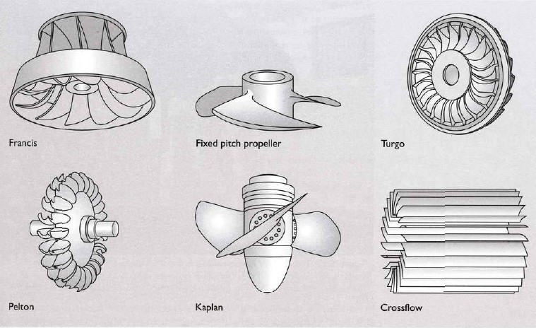
Pelton turbine or wheel is an impulsive turbine used mainly for high head hydroelectric schemes.The Pelton wheel is among the most efficient types of water turbines.The fluid power is converted into kinetic energy in the nozzles.The total pressure drop occurs in the nozzle. The resulting jet of water is directed tangentially at buckets on the wheel producing impulsive force on them.
Update; just found that on the iPhone in Settings > Photos there is an option 'TRANSFER TO MAC OR PC'. There are 2 alternatives 'Automatic' or 'Keep Originals'. 'Automatic' might force a conversion to JPG. 'Keep Originals' should retain your original format selected in Settings > Camera > Formats. I've got 'High Efficiency' selected.

When you sign up with your Apple Account, you can provide valuable feedback to other community members by upvoting helpful replies and User Tips.
3. Casing Steel coverings provided over the runner of pelton wheel is known as casing. It does not play any hydraulic function,but is necessary to provide the runner against accident. It has the following functions:
Update; I'm just found that there is an ImageCapture option called "Keep originals". Selecting this and it transfers all the photos in the original HEIC format with no problem.
The Kaplan turbine has adjustable blades and was developed on the basic platform (design principles) of the Francis turbine by the Viktor Kaplan in 1913. The main advantage of Kaplan turbines is its ability to work in low head sites which was not possible with Francis turbines.Kaplan turbines are widely used in high-flow, low-head power production.The Kaplan turbine is an inward flow reaction turbine, which means that the working fluid changes pressure as it moves through the turbine and gives up its energy. The design combines radial and axial features. The inlet is a scroll-shaped tube that wraps around the turbine’s wicket gate. Water is directed tangentially through the wicket gate and spirals onto a propeller shaped runner, causing it to spin. The outlet is a specially shaped draft tube that helps decelerate the water and recover kinetic energy. The turbine does not need to be at the lowest point of water flow, as long as the draft tube remains full of water. A higher turbine location, however, increases the suction that is imparted on the turbine blades by the draft tube that may lead to cavitations due to the pressure drop. Typically the efficiencies achieved for Kaplan turbine are over 90%, mainly due to the variable geometry of wicket gate and turbine blades. This efficiency however maybe lower for very low head applications. Since the propeller blades are rotated by high-pressure hydraulic oil, a critical design element of Kaplan turbine is to maintain a positive seal to prevent leakage of oil into the waterway. Kaplan turbines are widely used throughout the world for electrical power production. They are especially suited for the low head hydro and high flow conditions – mostly in canal based hydro power sites.
1. Spiral casing The spiral casing is the water conduit between the penstock and the regulating mechanism.The cross section through the spiral casing is continuously decreasing, the retardation in cross section causes an equal distribution of water into the guide vane cascade.In older designs the spiral casing was usually casted. For new designs it is commonly made by plate segments welded together. This has decreased the production cost and the transport expenses considerably without noticeably decreasing the efficiency.For vertical axis Francis turbines the spiral casing is usually embedded in concrete for increased support.
1) checked disk space and permissions on the target folder. 45Gbyte of free disk space and Read/Write access so no problems there.
So selecting these settings should maintain the original format when transferring to the mac using ImageCapture. Which avoids the problems caused by the HEIC to JPG conversion.
2) Why does ImageCapture on the mac pro transfer into JPG format whilst on the iMac it retains the HEIC format? I can't find an option setting for this anywhere.
Water flows from the penstock into the spiral casing. In the spiral casing the water is distributed around the complete periphery. The water is then guided by the stay vanes and guide vanes in the correct angle towards the runner. The guide vanes are adjustable and can change the angle depending on the inlet and outlet conditions of the turbine, they are controlled by a governor servo motor. The runner transfers the energy from the pressure and velocity in the water to a rotational momentum. The water exits through a draft tube that extracts the remaining energy in the water.The torque produced in the runner is transferred to a power producing generator through a shaft.
Nozzles direct forceful, high-speed streams of water against a rotary series of spoon-shaped buckets, also known as impulse blades, which are mounted around the circumferential rim of a drive wheel.As the water jet impinges upon the contoured bucket-blades, the direction of water velocity is changed to follow the contours of the bucket. Water impulse energy exerts torque on the bucket and wheel system, spinning the wheel,the water stream itself does a "u-turn" and exits at the outer sides of the bucket, decelerated to a low velocity. In the process, the water jet's momentum is transferred to the wheel and thence to a turbine. Thus, "impulse" energy does work on the turbine. For maximum power and efficiency, the wheel and turbine system is designed such that the water jet velocity is twice the velocity of the rotating buckets. A very small percentage of the water jet's original kinetic energy will remain in the water, which causes the bucket to be emptied at the same rate it is filled and thereby allows the high-pressure input flow to continue uninterrupted and without waste of energy. Typically two buckets are mounted side-by-side on the wheel, which permits splitting the water jet into two equal streams. This balances the side-load forces on the wheel and helps to ensure smooth, efficient transfer of momentum of the fluid jet of water to the turbine wheel.
2. Stayring and stay vanes The stay ring consist of an upper and lower ring connected by welded stay vanes.The stay vanes purpose is to absorb the axial forces on the inside of the spiral casing.The vanes are given a favourable hydraulic shape to affect the water flow minimally.
1) As the photos all transfer OK using a different account, a different computer and AirDrop, this implies that the photos on the iPhone are all OK. So what is it about my account settings that is fouled up?
The Francis turbine is a reaction turbine where water changes pressure as it moves through the turbine, transferring its energy. A watertight casement is needed to contain the water flow.Generally such turbines are suitable for sites such as dams where they are located between the high pressure water source and the low pressure water exit. Francis turbines are the most common water turbine in use today. They operate in a water head from 40 to 600 m (130 to 2,000 ft) and are primarily used for electrical power production.
taken by:http://syzjsd.en.alibaba.com/product/315463813-210167245 /old_hydro_power_plant_rebuild_with_new_water_turbine_generator_replace.html
Turgo turbine is an impulse turbine where water does not change pressure but changes direction as it moves through the turbine blades. The water's potential energy is converted to kinetic energy with a penstock and nozzle.
Also called a Michell-Banki turbine a crossflow turbine has a drum-shaped runner consisting of two parallel discs connected together near their rims by a series of curved blades. A crossflow turbine always has its runner shaft horizontal (unlike Pelton and Turgo turbines which can have either horizontal or vertical shaft orientation). Unlike most water turbines, which have axial or radial flows, in a crossflow turbine the water passes through the turbine transversely, or across the turbine blades. As with a waterwheel, water enters at the turbine's edge. After passing the runner, it leaves on the opposite side. Going through the runner twice provides additional efficiency. When the water leaves the runner, it also helps clean the runner of small debris and pollution. The cross-flow turbines generally operate at low speeds. Crossflow turbines are also often constructed as two turbines of different capacity that share the same shaft.The turbine wheels are the same diameter, but different lengths to handle different volumes at the same pressure.
1.Nozzle Nozzle of a pelton wheel is a circular guide mechanism which guides the water to flow at the desired directions.It also regulate the flow of water. A conical or spear needle operates inside the nozzle in axial direction. The main purpose of the nozzle is to regulate the flow of water through nozzle.When the needle is pushed forward into the nozzle, it reduces area if jet. As a result the quantity of water through the jet is also reduced. Similarly if the spear is pushed back out of nozzle, it increases the area of nozzle and discharge increases.The movement of spear is regulated by hand or by automatic governing arrangement.
3. Runner The runner consists of a hub, a shroud and runner blades connecting them. The runner converts the energy in the water to rotating motion and torque. The torque is transferred to the turbine shaft through a bolted friction joint or a combined friction/shear joint. The runner can either be casted or welded. For a welded design the hub and shroud is usually cast and welded together with hot pressed plate vanes.The number of blades depends upon the operating head. Runners with higher head will require a higher number of blades, this is mainly because of strength consideration. Increasing the number of blades reduce the pressure loading on the blade which will help to avoid cavitation and also prevent separation at the runner inlet during low loads. An increase in the number of blades also leads to more contact surface through the runner and thereby an increase in the friction losses.The thickness of the runner blades has to be large enough to withstand the hydraulic forces the blade is exposed to.For high head Francis turbines it is preferred to shape the blade in such a way that the main part of the hydraulic energy is utilized at the beginning of the blade. In this area the pressure difference from the pressure to the suction side will be large and thereby also the forces on the blade. It is therefore usual to have an increased thickness of the blade near the inlet and let the blade get thinner towards the outlet.
Francis turbines may be designed for a wide range of heads and flows. This, along with their high efficiency, has made them the most widely used turbine in the world. Francis type units cover a head range from 40 to 600 m (130 to 2,000 ft), and their connected generator output power varies from just a few kilowatts up to 800 MW.Large Francis turbines are individually designed for each site to operate with the given water supply and water head at the highest possible efficiency, typically over 90%.In addition to electrical production, they may also be used for pumped storage, where a reservoir is filled by the turbine (acting as a pump) driven by the generator acting as a large electrical motor during periods of low power demand, and then reversed and used to generate power during peak demand. These pump storage reservoirs, etc. act as large energy storage sources to store "excess" electrical energy in the form of water in elevated reservoirs. This is one of only a few ways that temporary excess electrical capacity can be stored for later utilization.
Looks like no one’s replied in a while. To start the conversation again, simply ask a new question.
Pelton wheels are the preferred turbine for hydro-power, when the available water source has relatively high hydraulic head at low flow rates, where the Pelton wheel is most efficient. Thus, more power can be extracted from a water source with high-pressure and low-flow than from a source with low-pressure and high-flow, even when the two flows theoretically contain the same power. Also a comparable amount of pipe material is required for each of the two sources, one requiring a long thin pipe, and the other a short wide pipe. Pelton wheels are made in all sizes. There exist multi-ton Pelton wheels mounted on vertical oil pad bearings in hydroelectric plants. The largest units can be up to 200 megawatts. The smallest Pelton wheels are only a few inches across, and can be used to tap power from mountain streams having flows of a few gallons per minute. Some of these systems use household plumbing fixtures for water delivery. These small units are recommended for use with 30 feet (9.1 m) or more of head, in order to generate significant power levels. Depending on water flow and design, Pelton wheels operate best with heads from 49–5,905 feet (14.9–1,799.8 m), although there is no theoretical limit. http://en.wikipedia.org/wiki/Pelton_wheel#Applications
The Turgo turbine is an impulse turbine designed for medium head applications. These turbines achieve operational efficiencies of up to 87%. Developed in 1919 by Gilkes as a modification of the Pelton wheel, the Turgo has certain advantages over Francis and Pelton designs for some applications. Firstly, the runner is less expensive to make than a Pelton wheel while it does not need an airtight housing like the Francis turbines. Finally the Turgo has higher specific speeds and at the same time can handle greater quantum of flows than a Pelton wheel of the similar diameter, leading to reduced generator and installation cost.Turgo turbines operate in a head range where the Francis and Pelton overlap. Turgo installations are usually preferred for small hydro schemes where low cost is very important.
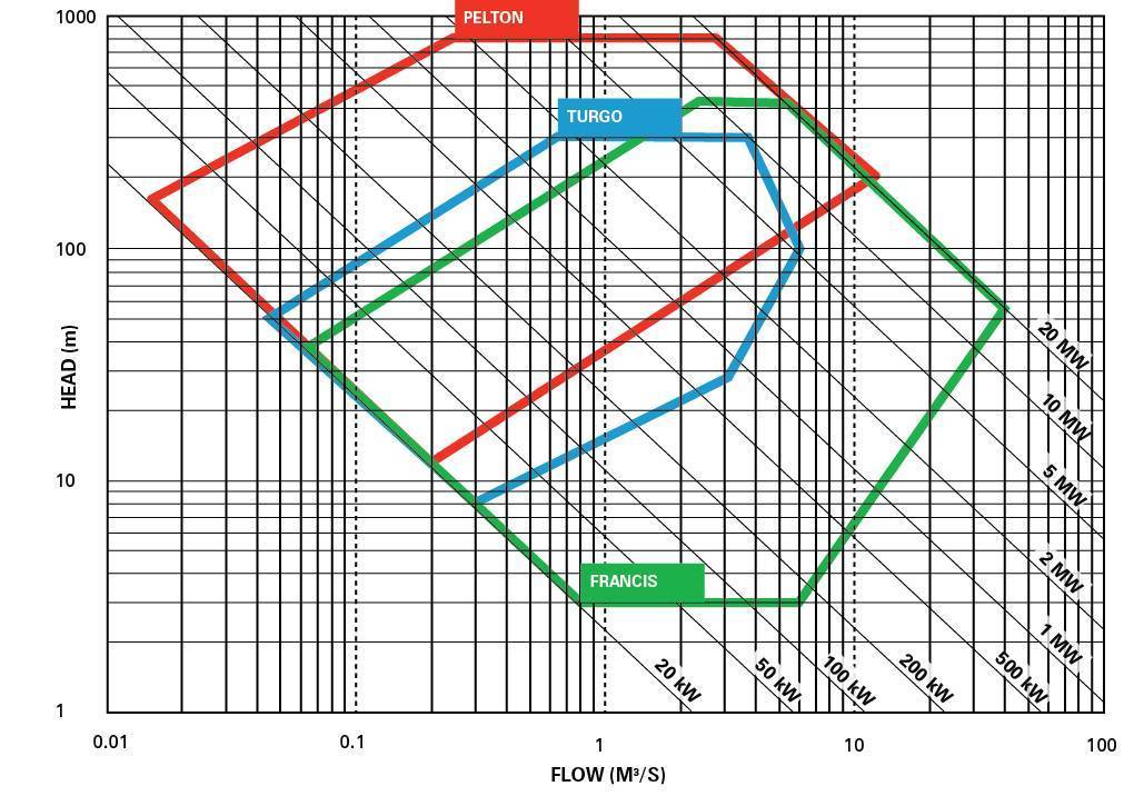
There are two main categories of hydro turbines: impulse and reaction,as described above. The type of hydropower turbine selected for a project is based on the height of standing water—referred to as "head"—and the flow, or volume of water, at the site. The most common type of impulse turbine is Pelton turbine.There are also Turgo turbine, Cross-flow turbine (also known as the Bánki-Michell turbine, or Ossberger turbine),Jonval turbine,Reverse overshot water-wheel,Screw turbine.On the other side,the most common reaction turbine is Francis turbine but there are also Kaplan turbine,Tyson turbine,Gorlov helical turbine.
Update; just found that on the iPhone in Settings > Photos there is an option 'TRANSFER TO MAC OR PC'. There are 2 alternatives 'Automatic' or 'Keep Originals'. 'Automatic' might force a conversion to JPG. 'Keep Originals' should retain your original format selected in Settings > Camera > Formats. I've got 'High Efficiency' selected.
4. Breaking jet Whenever the turbine has to be brought to rest the nozzle is completely closed. But the runner of pelton wheel goes on revolving due to inertia. To bring the runner to rest in short time, a small nozzle is provided in such a way that it will direct the jet of water on the back of buckets. It acts as a brake for reducing the speed of the runner.
Transferring photos and video using ImageCapture v8.0 from iPhone 11 Pro running iOS v14.71 to a mac pro running OSX Big Sur v11.5.2 connected by a genuine apple USB cable. ImageCapture converts the photos from HEIC format to JPG in Pictures/Adriani11
The runner is a circular disk carrying number of cup-shaped buckets which are placed at equal spacing around its circumference. Runner is generally mounted on the horizontal shaft with bearings and the buckets are either casted integrally with the disk or fastened separately. Buckets are made up of cast iron, bronze or stainless steel. Inner surface of the buckets are polished to reduce frictional resistance to the water jet.
When you sign up with your Apple Account, you can provide valuable feedback to other community members by upvoting helpful replies and User Tips.
5) Read all the other support posts I can find about the -9934 error. Seems lots of people have the problem but no-one has fixed it :-(
Figure 11:Another Pelton turbine or wheel. taken by:http://www.turbinesinfo.com/what-is-a-turbine/


 8613869596835