
Shop Tie Down Straps, Cam Buckles, and Accessories - cam roller
What sets us apart is not just the quality of our products but also our commitment to customer satisfaction. With less than 1% returns, QuickTrick tools boast a thoughtful design, meticulous manufacturing, and local tech support, providing users with confidence and reliability in their DIY alignment endeavors.
Here, the position of point (c) is computed using the center of rotation of the rigid body and it also serves as the origin for the body-fixed coordinate system.
From the above image, it is clear that the radius (r) and follower height (h) are functions of the angle of rotation and the follower rise function is simply a difference of cam profile from the base circle. The relation between them is defined as follows:
For our example, let’s consider a spring-loaded valve-opening mechanism that has a rocker arm and a radial cam. In this mechanism, the cam rotation is prescribed and a spring is attached to the valve to restrict its motion.
Cam andfollowerexamples
Variation of the cam-follower connection force with cam rotation (left) and torque required to rotate the cam shaft (right) for different values of the valve spring stiffness.
To understand the formulation, let’s take a look at an example of a cam and roller configuration in which both the cam and roller have been modeled as rigid components. For a rigid body, a point on the body can be located from the origin of a body-fixed (local) coordinate system (X, Y) by \vec{s}. Since the point is fixed to the body, the elements of the vector are constant in the body-fixed coordinate system, while in the global coordinate system, they vary with the rotation. The transformation from a local to global orientation is represented in terms of the rotation matrices.
When working with multibody systems, you may need to model a mechanism that transfers motion from one component to another. The mechanism used to implement this behavior, known as a cam-follower mechanism, plays an important role in many applications, including internal combustion engines, printing control mechanisms, textile weaving machines, and valves. You can easily model this type of mechanism with the Cam-Follower feature in the COMSOL® software. Let’s take a look at this feature in detail.
Camfollowermechanism
So, whether you’re an auto enthusiast or someone looking to take control of your vehicle maintenance without leaving the comfort of your home, QuickTrick’s DIY alignment kits are the ideal choice. Don’t procrastinate – optimize your garage with tools that guarantee accuracy, ease of use, and a fulfilling DIY alignment experience. Order your QuickTrick DIY alignment kit now and drive towards optimal vehicle performance.
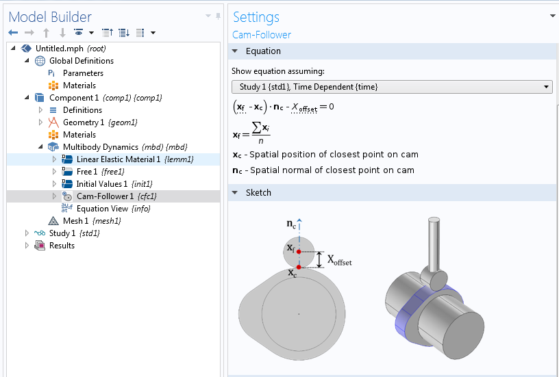
The Equation and Sketch for the Cam-Follower feature in COMSOL Multiphysics with the add-on Structural Mechanics Module and Multibody Dynamics Module.
Types of cam andfollowerpdf
Note: The Cam-Follower feature also requires the Multibody Dynamics Module, an add-on to the Structural Mechanics Module.
Out of the four valve stiffness values, only 20 kN/m and 30 kN/m can enforce a continuous contact between the cam and follower. To choose the optimal value of valve stiffness, we can look at the required torque plot. It can be observed in this plot that the required torque is less for a value of 20 kN/m, hence this is the optimal value of the valve stiffness among the values considered in this analysis.
For those who prefer a hands-on approach to vehicle maintenance and are looking for a dependable DIY alignment tool, QuickTrick DIY wheel alignment kits are a popular choice. QuickTrick stands out as the leader in the space of DIY car alignment and balancing, offering a range of tools and kits that empower enthusiasts to customize their wheel car alignment solutions at home. Unlike the complex and costly systems found in professional garages, QuickTrick’s DIY alignment kits and other tools are not only reasonably priced but also deliver accuracy comparable to high-end laser equipment.
With the default settings, the cam and follower will always remain in contact, which means that no chattering is allowed. To model intermittent contact, the Activation Conditions feature under the Cam-Follower joint type can be used. In addition, the cam and follower can both be modeled as rigid or flexible components.
What is a camshaft followerused for
In order to ensure that the point on the follower always follows the specified cam surface, an offset from the cam boundary is defined such that the gap distance is always zero. The implementation of these constraints follows this procedure:
Types of cam followers

Cam rollerfollower

The QuickTrick advantage extends beyond affordability. Our DIY vehicle wheel alignment tools are designed to be portable, user-friendly, and well-engineered, providing an optimal alignment experience.
Camfollowerbearing
In order to get a smoother surface representation, it is useful to increase the shape function order for the displacement to Quadratic. This applies both when the cam is rigid and when it is flexible.
The Cam-Follower joint type, available with the Multibody Dynamics Module as of COMSOL Multiphysics® software version 5.3a, is used to model applications in which a point follows a surface. In other words, the contact is unique and occurs at a single point.
The follower velocity first increases when the follower comes in contact with the opening flank region of the cam profile. Later, it decreases and becomes zero at the tip of the nose region. Similarly, it increases in the reverse direction and becomes zero when the follower comes in contact with the heal region of the cam profile. In COMSOL Multiphysics, the joint’s velocity and acceleration sign convention is decided based on the specified axis of the joint. It will be positive if the destination attachment is moving along the positive direction of the axis of the joint. For this case, the joint axis is defined along the z-axis, so the velocity is positive when the follower is moving upward and vice versa.
As the common contact point is not fixed with respect to the bodies (A) and (B), a constraint needs to be defined between the two bodies to maintain continuous contact.
A plot of the follower rise as a function of the cam rotation, after performing a simulation with the generated cam profile.
Usually, the active component is called the cam and the passive component is called the follower, but in the COMSOL® software, this feature is built in such a way that you can model both components as either active or passive.
By providing your email address, you consent to receive emails from COMSOL AB and its affiliates about the COMSOL Blog, and agree that COMSOL may process your information according to its Privacy Policy. This consent may be withdrawn.
If possible, use a fine mesh on a cam boundary to improve the accuracy of the mesh normal used in the Cam-Follower connection node.
Cam andfollowerDiagram
First, you need to create the interpolation function and enter the data for h vs. θ, also called the follower rise function. Thanks to the flexibility of the COMSOL® software, one can directly import the follower rise function. After importing the follower rise function, the cam surface can be generated using the parametric curve. For this, one needs to first determine the base circle radius and then express the radius that depends upon the follower rise function and base circle radius. The parametric form is similar to that of a circle; the only difference in this case is that the radius is a function of θ. To do this in COMSOL Multiphysics, one can use the interpolated function to create the follower rise function and further use them under the parametric curve to define the value of r (the radius of the cam surface). Usually, the data is a piecewise curve, so it is good practice to create different profile curves for each section of outstroke, upstroke, and dwell. Finally, you use the Convert to solid option to generate the cam profile.
Now, if the follower rise function is known, the variation of the radius (r) will represent a circle for each value of θ. So, it will give a family of curves. In order to generate the cam profile, we need to plot the envelope of the curves. This can be easily done in COMSOL Multiphysics using the Parametric Curve option.
In COMSOL Multiphysics, the constraint is defined on the vector d such that its magnitude in the normal direction of the closest point on the cam surface is equal to the offset value.
One of the main objectives behind mounting the spring on the valve is to force the follower to follow the cam profile and to avoid intermittent contacts between the cam and follower. Hence, the optimal value of the valve spring stiffness should enforce the contact between the cam and follower at all times, while simultaneously requiring the least torque to rotate the cam shaft.
When the rotary motion of the cam is converted into oscillatory motion, the configuration is known as a rotating cam and oscillatory follower.
The cases in which the motion of the follower is a combination of different types of analytical expressions, such as uniform motion, parabolic motion, simple harmonic motion, cycloidal motion, or general polynomial motion. In these cases, the cam profile can be easily created using the Analytic Function feature with a combination of different motions for the full cam rotation. The analytic function allows a symbolic expression, so you can directly write it as a function of θ.
In this case, both the cam and follower exhibit translational motion. This means that the motion to the follower is due to the profile height of the cam.
There are many ways to transform one type of motion into another. The variety of the cam-follower mechanism is limited only by your own imagination. For example, you can use a combination of the above configurations to generate a combined effect. A few common examples are barrel cams and end cams, which are used to convert rotary motion into translational and oscillatory motion.
The Structural Mechanics Module contains advanced tools for mechanical analyses. See what other types of analysis are possible by clicking the button below.
You can see that the acceleration values are negative in the range of 60° to 120° of cam rotation. This is the region where the follower has a tendency to leave the contact with the cam profile, which depends on the valve spring stiffness value for a given camshaft RPM. By plotting the connection force vs. cam rotation, you can check which spring ensures continuous contact. The contact force sign convention is positive if the cam and follower are no longer in contact, while the negative value shows that the contact is still maintained.
Cam-follower mechanisms are categorized based on the input and output motion of their configurations. The different types of cam-follower mechanisms are described below.
If you’ve ever visited a cutting-edge car repair garage offering car alignment services, you’ve likely encountered the mysterious world of high-tech, computer-operated systems claiming laser-guided precision – all of which may seem daunting and, often, expensive. However, the key to understanding and performing wheel alignment lies in three crucial terms: caster, camber, and toe angles. These parameters collectively ensure smooth vehicle operation, optimize tire lifespan, and enhance predictable handling.
Let’s take a simple example to illustrate this concept. Consider a simple knife edge radial follower with a known follower rise and a cam angle rotation. The rise function is such that there is outstroke during 60° of cam rotation, dwell for the next 30° of cam rotation, return stroke during the next 60° of cam rotation, and dwell for the remaining 210° of cam rotation.
There are cases in which the cam is stationary and the follower traces the profile of the cam. This type of arrangement is classified as a stationary cam and moving follower.
When a follower moves along a guide while a cam rotates, the motion is categorized as a rotating cam and translating follower. This is further categorized based on the motion of the follower. If the motion is along the axis passing through the center of rotation of the cam, then it is called a radial inline follower, whereas if the motion is along an offset from the axis, it is called a radial offset follower.
The comprehensive selection of QuickTrick’s offerings includes the NEW 5th Gen QuickTrick QuickString for 4-wheel alignment, QuickTrick Caster/Camber Kit, QuickTrick Toe Alignment Kit, ATV UTV SXS Alignment Kit, Turnplates made of US STEEL, and the QuickTrick Steering Wheel Holder. Each of these tools is crafted with precision and quality, ensuring a seamless alignment process for home mechanics.
One problem with cam design is to determine the cam profile suitable to generate the desired motion of follower. In COMSOL Multiphysics, one can easily create a geometry based on the follower rise function. The follower rise function is defined as the displacement of the follower with change in the cam rotation. The first step is to derive the radius as a function of the follower rise function. This relationship can be established using the analytical approach if the follower rise function is preknown. The analytical approach is quite simpler than the graphical approach of creating the cam surface, because the follower rise function is usually a combination of different elementary functions. Also, in a few cases, the desired output motion of follower is already known so it became simple to generate a cam profile from the known follower rise function.


 8613869596835