
Wheel Bearing Troubleshooting and Repair - GMB Blog - where to get wheel bearings replaced
Use a motor sizing tool. After completing a motor sizing, our technical support engineers are able to walk you through the product selection process if necessary.
Johann Tang is a Product Specialist at Oriental Motor USA Corp. Before joining the marketing team, he spent 15 years in sales, technical application support, and training of various types of fractional horsepower electric motors, gear motors, actuators, drivers, and controllers. If you have any questions, please feel free to use the live chat window, 1-800-GO-VEXTA (1-800-468-3982), or techsupport@orientalmotor.com, to reach our product support team. Johann can be reached via LinkedIn. Sorry, comments have been turned off.
As I have mentioned before, a successful motor sizing is only as good as the information provided. Users often oversize motors because either they do not know the exact information necessary for sizing, or they want to extend the life of the motor.
Similar to dynamic and static moment loads, a radial load or an axial load also have both dynamic and static components. The table above is used to determine both.
Radial loadvs axialload
If you're interested in a service life estimation based on bearing life, please contact our knowledgeable technical support engineers.
One side of the bearing rotates with the wheel while the other side is fixed to the suspension. The rolling elements in bearings carry vehicle load and ensure minimal-friction rotation between the inner and outer races. In automotive bearings, there are two types of rolling elements: ball bearings and roller bearings.
Ball bearings are used in applications where speed is more important than load. They have a small point of contact, which provides less rolling resistance and lighter load carrying capabilities.
The output shaft bearing in the gearhead is typically bigger than the output shaft bearing in the motor because the load on the gearhead shaft would be much bigger than the load on the motor shaft.
Oriental Motor offers an extensive product line-up of about 50,000 different products that provide the optimal motion system. For over a century we have concentrated on technological advancement and product design improvement. This emphasis is evident in the sophisticated devices that we market today. Oriental Motor's sales and service network is international, with offices throughout North America, Europe and Asia.
Radial loadbearing
In the above table, you can see that the radial load changes according to the "distance from the end of the gearhead output shaft". This is the distance from the end of the load shaft to the point at which force is applied to the shaft (also the location of the installed load). The permissible radial load increases as the distance from the end of the shaft increases because this also means that the load is closer to the support bearing located right inside the gearhead flange. More load can be supported if the load is "hung" closer to the support bearing, which is the fulcrum is this case.
PS: This table lists permissible radial and axial loads only for common geared AC motors. When a chain, gear, belt, etc. is used as the transmission mechanism, the radial load is always applied on the gearhead shaft. For stepper motors, the permissible radial and axial loads for the motors are shown.
Overall, it is important to understand the type of bearing you are working with and to follow the proper installation procedures using the appropriate tools. Always tighten with a torque wrench to the correct torque specifications so the bearings are set to the proper preload.
I'm working on a chain and toothed (sprocket) conveyor and using a 2IK6 motor with 360:1 gearhead. I need 10 N·m of torque on an 0.1 meter (effective) diameter sprocket. I'm guesstimating that the chain tension is about 10 N. I only intend to rotate in one direction. My sprocket is mounted 10 mm from the end of the shaft.
Radial loadexample
Topics: AC Motors, Stepper Motors, Speed Control, Motor Sizing, BLDC Motors, Gearheads, Servo Motors, Motion Control Basics
Most motor sizing software do not consider axial or radial loads, so don't forget to confirm your radial load and axial load after sizing your motor.

Manufacturers may show these specifications differently. Typically, a table (see example below) lists permissible radial loads and axial loads according to the gearhead size and the gear ratio. While the permissible axial load remains the same, the permissible radial load varies by the "distance from the end of the gearhead output shaft".
Radial Load is defined as the maximum force that can be applied to the shaft in the radial direction (any direction perpendicular to the motor shaft axis). Radial load is also referred to as the "overhung load" because of how the load may "hang" off the shaft. Radial loads vary by the distance between the installation point of the overhung load to its support bearing.
To begin your motor sizing consultation with us, please use our , select one of the common applications (shown below), then fill in the blanks. A sizing report, including calculations, can be generated. Our knowledgeable technical support engineers are more than happy to analyze your motor sizing report with you to make sure you buy the right motor the first time (we do not like RMAs either).
Axialloadbearing
Static radial load would be belt tension. The 10 N was a guesstimate, but that's the best information we have right now, so we'll use it. At 10 mm from the end of the shaft, our maximum radial load for the 2IK6 motor is 200 N, so we're good here.
How early the life may end will be proportional to how much these specifications are exceeded by and how long. For example, since our ball bearings are rated for 10,000 hour life, exceeding either radial or axial load specifications by 10% may reduce its life by about 1,000 hours.
Radial loadformula
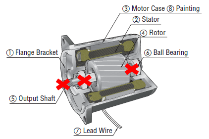
The structural strength of a motor comes from the combined mechanical rigidity of its case, flange brackets, and output shaft assembly. For a gear motor, it also includes the gears and additional bearings. However, the bearings located closest to the load "bear" most of this burden. Needless to say, the radial and axial load specifications of a motor or gearhead has a lot to do with its bearings.
For radial loads, there is an addtional component of "dynamic" radial load, which is the radial load when in motion. Also make sure the calculated value is under the value in the chart (see above).
Since we live in a perfect world, all the variables that are necessary for the calculation are laid out and provided in the preferred units. In reality, it usually takes more work. For example, notice that the load coefficient and the service factor were not given, but the drive method and type of load were given. Also, the values provided may be in different units, so an extra step of unit conversion may be needed.
What isaxialload
In most cases, a thorough motor sizing takes more work than you think. If your time is as valuable as we think it is, let our experts help!
For example, if the permissible radial load is exceeded, then the shaft may start bending and ultimately break. If the permissible axial load is exceeded, then the motor or gearhead bearing may deteriorate and ultimately fail. Either way, the motor would cease operation or suffer decreased life. The supporting element closest to the load is typically the first component to break.
We show the internal structure of an AC motor and its gearhead below. The same axial load and radial load concepts apply to all types of motors.
Both radial and axial load specifications are related to the strength, or mechanical rigidity, of the bearings, shaft, and case assembly. Exceeding these specifications may result damaging the ball bearings, such as flaking from the raceway and rolling elements, or breaking the output shaft.
The images below shows an illustration of both radial load (overhung load) and axial load (thrust load) forces acting on a shaft of a motor and a gearhead.
A motor's performance characteristics are described by its torque and speed specifications. A motor's structural strength is described by its radial load and axial load specifications. A motor's torque and speed specifications indicate if a motor can perform a task. A motor's radial load and axial load specifications indicates how long the motor can perform the task.
Thrustloadvsradial load
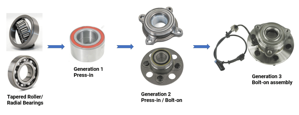
Wheel bearings have a very important job – enabling the rotation of your wheels. They make sure your wheels run smoothly with minimal friction. They also maintain correct wheel tracking and can even play a role in providing your vehicle’s drive systems with wheel speed sensor signals. gina fitness desnuda películas para adolescentes oximetolona ciclo deltoides mediales – fitness at home – ejercicios en vídeo gratuitos Over the years, three generations of wheel bearings have been developed. In our on-demand webinar, our experts take you inside all three generations to provide expert service advice and must-know installation procedures.
Other factors, such as drive method and load type, need to be considered for radial load. When using a flat belt drive method, for example, the radial load value increases.
Roller bearings, on the other hand, have a large point of contact, which makes them ideal for carrying higher loads. These bearings have many shapes and come in cylindrical, spherical, tapered and needle styles.
Axial andradial loadbearing
Take a look at the belt conveyor application example below. How would you calculate the value of required radial load that you'll need from the motor?
[fa icon="calendar"] Originally posted on Mar 31, 2020 7:58:57 PM Last updated on September 25, 2024 / by Johann Tang
For example, if a motor has a 100 N axial load specification, it means that the motor can hang a 100 N load from its shaft (if the shaft is facing down), or support a load on its shaft (if the shaft is facing up). 100 N (Newtons) equates to about 10 kg.
Axial Load is defined as the maximum force that can be applied to the shaft in the axial direction (in the same axis as or parallel to the motor shaft axis). Axial load is also referred to as the "thrust load" since thrust force and thrust load are forces acting upon the exact same axis. A typical axial load is about half the motor weight, although that has increased over the years.
As for service factor, which relates to operating conditions, factors such as frequent starting and stopping of the load as well as changing of rotation direction can affect the radial load.
Besides load torque, acceleration torque, speed, and load inertia, overlooking certain sizing parameters during the motor sizing process can literally make or break your machine.
For example, a static radial load includes the weight of the pulley and belt tension at rest. A dynamic radial load, which requires calculation, includes forces from the same pulley weight and belt tension while in motion. A static axial load would be the weight of the pulley if the motor shaft is in the vertical orientation. A dynamic axial load would be lower than the static axial load, so typically only the static axial load is considered. Make sure that the values are under the published values in the chart.
When pulleys, belts, gears, sprockets, chains, etc. are used as the transmission mechanism, the dynamic radial load is calculated with the following equation.
To check for internal damage of a motor or a gearhead, you can remove power and disassemble the motor from gearhead, then manually rotate the shaft clockwise and counterclockwise. If the motor or gearhead is damaged, you would feel a different resistance from one direction to another, hear abnormal noise, or not be able to rotate the shaft at all.
Static axial load is actually unknown at this point, but looking at the application image, we should not have a lot of static axial load, and it definitely should be below the 40 N value in the chart, so we're good here, too.
Since 1982, Mevotech has been helping technicians make the best auto part decisions by offering innovative products with advanced technology, extensive coverage and industry-leading customer support.
With a belt conveyor, the motor torque provides the driving force that generates work. This is shown as T, which is the amount of torque in N·m. If we consider y (effective radius in meters) to be the radius of the pulley, then we can calculate radial load or W (amount of work).
For increased part service life and performance, the best wheel hub assemblies are engineered with a stiff roll-formed assembly, feature precision rolling elements and raceways, come pre-loaded with nanoceramic grease and are protected by advanced sealing and coating technology. They are also designed for a quick and complete fitting, with hardware and torque specs in the box.


 8613869596835