
Go-Kart Font Hub Bearing - go kart wheel bearing
For the guidance and support of a rotating part, two or more rolling bearings are mounted at a defined distance onto the part and retained by a housing. An exception to this are rolling bearing types that are able to absorb a torque, such as two-row angular contact ball bearings, taper roller bearings or also cross-roller bearings.
In the case of an optimally loaded roller bearing, the circumferential speed in the contact area is the same for all rolling elements. The rolling elements roll smoothly over the raceway. In certain speed and load ranges, e.g. when starting up a machine without load, there is a sliding motion between the surface of the rolling element and the raceway. In bearing terminology, this is called slippage. It occurs frequently with varying or high rotational speeds in combination with small loads. Slippage leads to damage on the running areas of the rings and of the rolling elements. This reduces the working life of the bearing.
Shaft deflection has a significant impact on the smooth running of rolling bearings and their life expectancy. Many rolling bearings, particularly cylindrical rolling bearings, can support a limited amount of shaft deflection. If the deflection is greater than the bearing is designed to handle, stress at the ede of the rollers will become excessive and lead to premature failure.
In order to facilitate the selection of a suitable bearing arrangement, the advantages and disadvantages of the various bearings are discussed below, taking into account different loads and speeds. This is intended only to help with the decision and does not claim to be complete.
In special cases it is also possible to adjust deep groove ball bearings inversely facing each other. The deep groove ball bearing is then regarded as an angular ball bearing with a contact angle. Another special case is mounting an axial bearing against an angular contact bearing or a deep groove ball bearing.
Slippage is particularly common with roller bearings. To avoid it, it is important to adhere to the minimum load. The formulas for calculating the minimum load can be found in the respective product specifications.
The roller bearing’s capacity to transmit axial or radial forces depends primarily on the contact angle α0 . Therefore, when selecting a bearing with a suitable contact angle, the ratio of the axial load to the radial load must be checked.
Mounting using a locating or floating bearing is the most common type of mounting arrangement. A locating bearing is defined as a bearing (pair) which supports the forces on a rotating part both axially and radially.
The locating bearing side below consists of two bearings. The axial force is supported solely by a four point contact ball bearing which has to be designed radially movable. The type NU or N is suitable for the cylindrical roller bearing as a sole radial bearing. To prevent the four point contact ball bearing from carrying any radial load, it is important that the radial gap between the outer diameter of the four point contact ball bearing and the housing bore is larger than the internal clearance of the cylindrical roller bearing.
The sliding fit is always placed on the ring receiving a point load. Whether the inner or outer ring is adjusted depends on the mating structure (e.g. locknut, housing lid). In order to ensure easy adjustment, the fitting position of the bearing ring must also be taken into account.
In order to absorb larger shaft deflections, the use of barrel roller bearings, spherical roller bearings and self-aligning ball bearings is recommended.
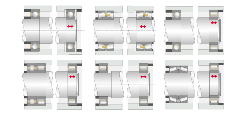
In the O-arrangement, the tips of the cones formed by the pressure lines point outwards, forming an “O”. In the X-arrangement, they point inwards and thus form an “X”
For cylindrical roller bearings, the types NUP or NJ + HJ are suitable as locating bearings and NU for non-locating bearings. Alternatively, a non-locating bearing arrangement consisting of two NJ cylindrical roller bearings can be implemented.
If the roller cone lines do not intersect, the axial heat expansion has a stronger effect on the bearing clearance than the radial expansion. The set clearance gets bigger.
The table below shows an overview of a bearing selection for a shaft with two bearing positions. The distances of the bearing positions to the load application are the same and thus assume an ideal state. The table specifies rotational speed as well as radial and axial load as criteria.
A floating bearing arrangement with two spherical roller bearings is frequently used in heavily loaded shafts. In addition to the high loads, it can also tolerate large shaft bendings and misalignment. The following figure illustrates a typical arrangement.
In the case of large axial forces, the axial portion is supported separately within the locating bearing. This is similar to a locating bearing arrangement with component separation that was already shown. In order to compensate for the shaft deflection, spherical roller thrust bearings are used as thrust bearings (instead of four point contact ball bearings) and radial spherical roller bearings are used as radial bearings. In terms of design, please note that the pivot radii of the spherical roller thrust bearing and the radial spherical roller bearing must be concentric.
A floating bearing is a bearing which only bears radial loads. In the axial direction it is able to compensate for longitudinal expansion of the shaft or housing either by its inner geometry (e.g. cylindrical roller bearing) or through a sliding fit.
The support base H is larger in the O-arrangement than in the X-arrangement with the same bearing distance. The width of the support base has a significant impact on the ability to support tilting moments and the tilting rigidity of the bearing arrangement.
The floating bearing arrangement is similar to the adjusted bearing arrangement. However, this type of arrangement aims for an axial clearance, so that the rotating component “floats” axially between the bearings. The axial clearance has to be set in such a way that it is not completely eliminated under unfavorable thermal conditions.
If the roller cone lines coincide, the axial and radial heat expansions balance each other out and the set clearance is preserved.
If the roller cone lines intersect, the radial expansion has a stronger effect on the bearing clearance than the axial heat expansion. The set clearance becomes smaller.
From the design aspect, ensure that the bearing in the non-locating bearing position has a sliding fit. This must at least compensate for the thermal length expansion of the shaft/housing without creating constraining forces. The following figure shows a typical setting.
One ring – in most cases the outer ring – contains a sliding fit. For cylindrical roller bearings, type NJ/NJP this is not necessary. Here, the length adjustment happens within the bearing.
In the case of an adjusted bearing arrangement, the bearings (frequently angular ball bearings, tapered roller bearings) are set to axial clearance or preload by moving the bearing rings. Angular ball bearings must always be mounted in pairs inversely, because a radial load always creates an axial force that has to be supported by a counter bearing.
The impact of the operating temperature must be taken into account when adjusting the clearance or the preload of the tapered roller bearings or angular contact ball bearings. It must be ensured that the required clearance or preload values are achieved during operation, i.e. when warm. Both variants are characterized by a high rigidity of the bearing.
Another decisive factor is heat expansion. In an X-arrangement, if the shaft is warmer than the housing (TH < TS) the adjusted axial clearance gets smaller . The graphic below shows an X-arrangement with tapered roller bearings. The point “R” depicts the roller cone apex. This is the intersection point of the extension of the outer ring raceway with the bearing axis.


 8613869596835